LS-Support-Interfaces@jungheinrich.de
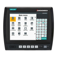
Power supply connector
The device is supplied with 12 V to 48 V DC via a 4-pole
plug (Phoenix Contact MC 1.5/ 4-STF-3.81), depending
on the version.
1. PE
2. 0 V DC
3. Ignition (+12 bis 48 V DC)
4. +12 bis 48 V DC
NOTE – PE Protective earth and fuse
The protective earth conductor must always be attached.
Without a protective earth conductor, there is a risk of overvoltage on the device.
The power supply must be provided with a fuse:
7 A at 12 V DC; 4 A at 24 V DC; 2 A at 48 V DC.
Ignition (IGN)
The device starts automatically when the voltage is applied to the Ignition input.
The supply voltage must be constant. The permissible voltage at the IGN input corresponds to the
supply voltage of the device.
Further reactions to state changes at the Ignition input can be defined in the corresponding module of
the Configuration Center, see section 6.2.
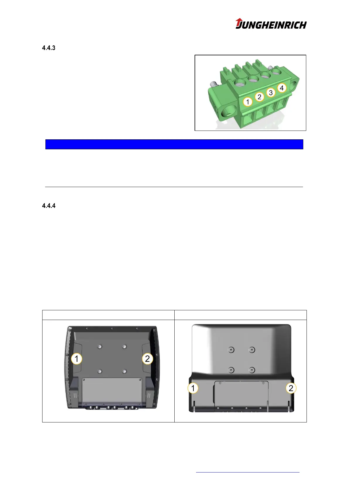
4.5 Antennas WLAN and Bluetooth
The two antennas for 2.4 and 5 GHz WLAN and Bluetooth are protected behind the two plastic covers
on the back of the device.
Avoid covering the antennas with metal parts during installation.
The option "external antenna" deactivates the internal antenna at the rear right (2) and offers it exter-
nally in the service slot via an R-SMA connector.
 Loading...