Audio Recording
You can record audio from the four channels
(CH-1/CH-2/CH-3/CH-4) in synchronization with
the video images on this camera recorder.
Select from the three options below to record the
audio.
0
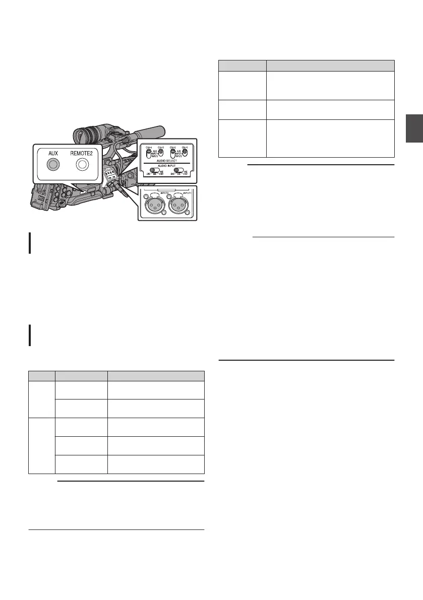
Microphone connected to [AUX] terminal
0
Microphone connected to [INPUT1] terminal
0
Microphone connected to [INPUT2] terminal
.
Setting the Number of Recording
Channels
0
Set accordingly for slot A and slot B.
0
Set the number of recording channels in [Main
Menu] B [System] B [Record Set] B [Record
Format] B [WAudio]/[YAudio].
(A P133 [ W Audio ] )
(A P134 [ Y Audio ] )
Selecting Audio to Be Recorded in Each
Channel
Select the audio to be recorded in CH-1/CH-2/
CH-3/CH-4.
-
Switch Setting Audio Input
CH-1
CH-3
AUX Audio input from [AUX]
terminal
INPUT1 Audio input from [INPUT1]
terminal
CH-2
CH-4
AUX Audio input from [AUX]
terminal
INPUT1 Audio input from [INPUT1]
terminal
INPUT2 Audio input from [INPUT2]
terminal
Memo :
0
Set the reference input level of “AUX” using
[Main Menu] B [A/V Set] B [Audio Set] B [AUX
Gain].
(A P127 [ AUX Gain ] )
Setting for [INPUT1]/[INPUT2] Input Channel
Set [AUDIO INPUT] signal selection switch 1 or 2
according to the devices to be connected to the
[INPUT1] and [INPUT2] terminals.
Setting Description
[LINE] Use this setting when connecting to
an audio device or other equipment.
The reference input level is +4 dBu.
[MIC] Use this setting when connecting to
a dynamic microphone.
[MIC+48V] Use this setting when connecting to
a microphone (phantom
microphone) that requires a +48 V
power supply.
Memo :
0
When “MIC” or “MIC+48V” is selected, set the
reference input level in [Main Menu] B [A/V
Set] B [Audio Set] B [Input1 Mic Ref.]/[Input2
Mic Ref.].
(A P127 [ Input1 Mic Ref. ] )
(A P127 [ Input2 Mic Ref. ] )
Caution :
0
When connecting a device that does not require
a +48 V power supply, make sure that it is not
set to the “MIC+48V” position.
0
When the [AUDIO INPUT] signal selection
switch 1 or 2 is set to “MIC”, check to ensure that
a microphone is connected to the [INPUT1]/
[INPUT2] terminal. If you increase the recording
level when a microphone is not connected,
noise from the input terminal may be recorded.
0
When a microphone is not connected to the
[INPUT1]/[INPUT2] terminal, set the [AUDIO
INPUT] signal selection switch 1 or 2 to “LINE”.
Audio Recording
69
Shooting
 Loading...