(No.YA098) 1-21
p
r
s
t
u
v
q o
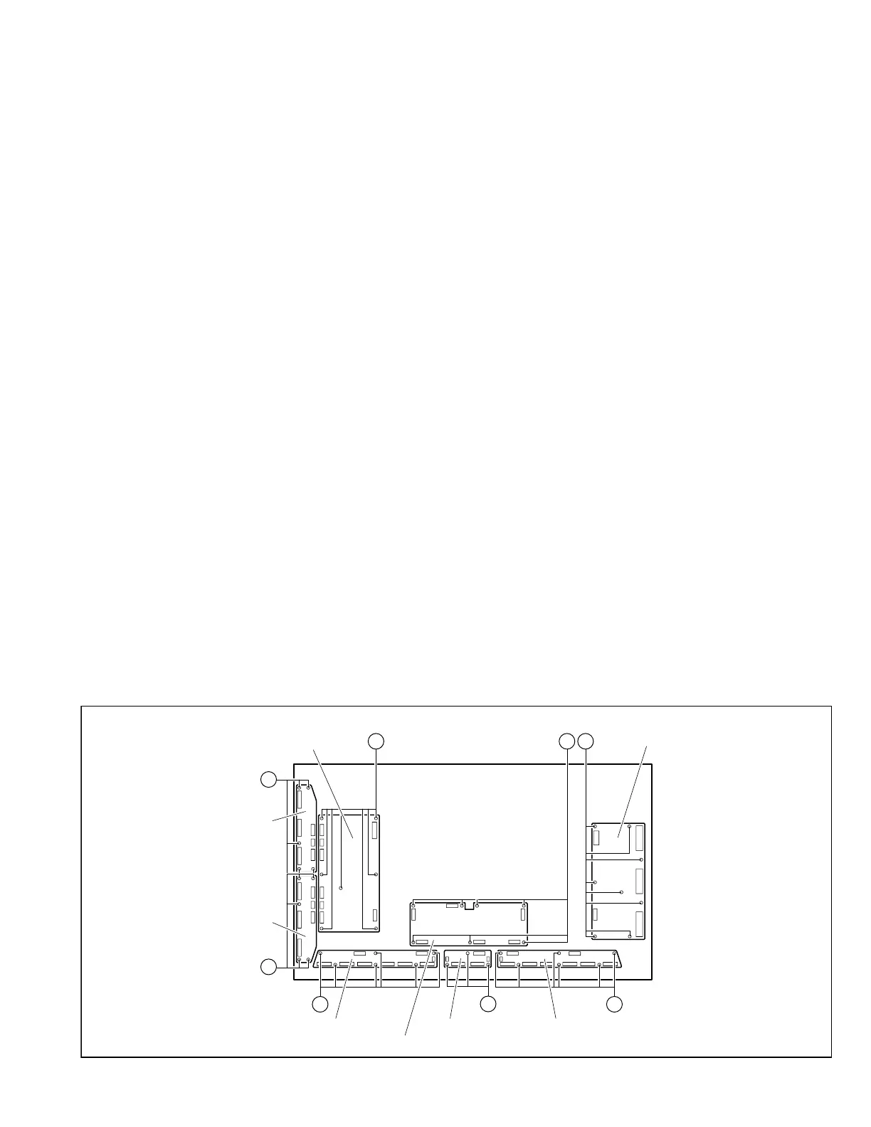
E-BUFFER PWB G-BUFFER PWBF-BUFFER PWB
X-MAIN PWB
LOGIC-MAIN PWB
Y-MAIN PWB
Y-BUFFER-U
PWB
Y-BUFFER-L
PWB
(x7)
(x5)
(x5)
(x6)
(x3)
(x6)
(x7) (x8)
Fig. 4
3.1.18.5 REMOVING THE Y-BUFFER-L PWB (Fig.4)
• Remove the PDP UNIT.
(1) Disconnect the connectors [CN5501], [CN5502],
[CN5503], [CN5504], [CN5505], [CN5506] from the Y-
BUFFER-L PWB.
(2) Remove the 5 screws [s], and remove the Y-BUFFER-L
PWB.
NOTE:
• It is advisable to take note of the connecting location
(connector number) of the removed connectors.
3.1.18.6 REMOVING THE E-BUFFER PWB (Fig.4)
• Remove the PDP UNIT.
(1) Disconnect the connectors [CN401], [CN806], [EC1], [EC2],
[EC3], [EC4], [EC5], [EC6], [EF1] from the E-BUFFER PWB.
(2) Remove the 6 screws [t], and remove the E-BUFFER PWB.
NOTE:
• It is advisable to take note of the connecting location
(connector number) of the removed connectors.
3.1.18.7 REMOVING THE F-BUFFER PWB (Fig.4)
• Remove the PDP UNIT.
(1) Disconnect the connectors [CN402], [FC1], [FC2], [FE1],
[FG1] from the F-BUFFER PWB.
(2) Remove the 3screws [u], and remove the F-BUFFER PWB.
NOTE:
• It is advisable to take note of the connecting location
(connector number) of the removed connectors.
3.1.18.8 REMOVING THE G-BUFFER PWB (Fig.4)
• Remove the PDP UNIT.
(1) Disconnect the connectors [CN403], [GC1], [GC2], [GC3],
[GC4], [GC5], [GC6], [GF1] from the G-BUFFER PWB.
(2) Remove the 6 screws [v], and remove the G-BUFFER PWB.
NOTE:
• It is advisable to take note of the connecting location
(connector number) of the removed connectors.
3.1.18 REMOVING THE PWB IN PDP UNIT
3.1.18.1 REMOVING THE X-MAIN PWB (Fig.4)
• Remove the PDP UNIT.
(1) Disconnect the connectors [CN4001], [CN4002],
[CN4003], [CN4004], [CN4005] from the X-MAIN PWB.
(2) Remove the 8 screws [o], and remove the X-MAIN PWB.
NOTE:
• It is advisable to take note of the connecting location
(connector number) of the removed connectors.
3.1.18.2 REMOVING THE Y-MAIN PWB (Fig.4)
• Remove the PDP UNIT.
(1) Disconnect the connectors [CN5001], [CN5002],
[CN5003], [CN5004], [CN5005], [CN5006], [CN5007],
[CN5008] from the Y-MAIN PWB.
(2) Remove the 7 screws [p], and remove the Y-MAIN PWB.
NOTE:
• It is advisable to take note of the connecting location
(connector number) of the removed connectors.
3.1.18.3 REMOVING THE LOGIC-MAIN PWB (Fig.4)
• Remove the PDP UNIT.
(1) Disconnect the connectors [CN101], [CN201], [CN401],
[CN402], [CN403], [CN803] from the LOGIC-MAIN PWB.
(2) Remove the 7 screws [q], and remove the LOGIC-MAIN
PWB.
NOTE:
• It is advisable to take note of the connecting location
(connector number) of the removed connectors.
3.1.18.4 REMOVING THE Y-BUFFER-U PWB (Fig. 4)
• Remove the PDP UNIT.
(1) Disconnect the connectors [CN5401], [CN5402],
[CN5403], [CN5404], [CN5405], [CN5406] from the Y-
BUFFER-U PWB.
(2) Remove the 5 screws [r], and remove the Y-BUFFER-U
PWB.
NOTE:
• It is advisable to take note of the connecting location
(connector number) of the removed connectors.
 Loading...