(No.YA098) 1-23
3.2 DISASSEMBLY PROCEDURE [35V MODEL]
CAUTION:
• When exchanging parts etc. with the front side (PDP side)
facing down, please place a protection sheet below before
starting, so as to prevent scratches on the front side.
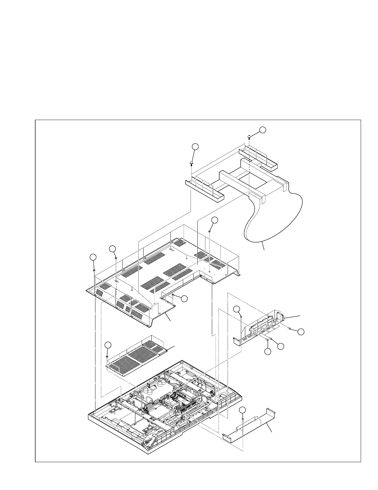
3.2.1 REMOVING THE REAR COVER (Fig.6)
(1) Remove the power cord.
(2) Remove the 2 screws [A] and the 6 screws [B].
(3) Remove the TABLE TOP STAND. [PD-35B50BJ]
(4) Remove the 2 screws [c]. [PD-35B50BU]
(5) Remove the 14 screws [D], the 6 screws [E] and the 8
screws [F], and remove the REAR COVER.
3.2.2 REMOVING THE TERMINAL COVER AND CENTER COVER
(Fig.6)
• Remove the REAR COVER.
(1) Remove the 6 screws [G], and remove the CENTER
COVER.
(2) Remove the 7 screws [H], and remove the CHASSIS
SHIELD COVER.
(3) Remove the 8 screws [I], the 6 screws [J] and the 1 screw
[K], and remove the TERMINAL COVER.
A
B
(x2)
(x6)
TABLE TOP STAND
D
H
TERMINAL
COVER
F
E
G
J
I
K
I
REAR COVER
(x14)
(x6)
(x8)
C
(x2)
(x7)
(x6)
(x6)
(x6)
CHASSIS
SHIELD COVER
CENTER COVER
Fig. 6
[PD-35B50BU]
[PD-35B50BJ]
 Loading...