(No.YA098) 1-45
Item
Measuring
instrument
Test point Adjustment part Description
1125i
A-D OFFSET
[1. ADJUST]
S001:PREPARE
(adjustment setting
mode change)
S013:HD CB OF
(1125i blue offset)
S014:HD CR OF
(1125i res offset)
S030:R DRIVE
(Red drive)
S031:G DRIVE
(Green drive)
S032:B DRIVE
(Blue drive)
(1) Receive a 1125i (50 Hz) 30% all-white pattern signal.
(2) Set PICTURE MODE to “STANDARD”.
(3) Select “1.ADFJUST” from the SERVICE MENU.
(4) Set < S030 > (Red drive), < S031 > (Green drive) and
< S032 > (Blue drive) to set “255”.
(5) Set < S001 > (adjustment setting mode change) to
set “013” and it change to the 1125i A-D offset
adjustment setting mode.
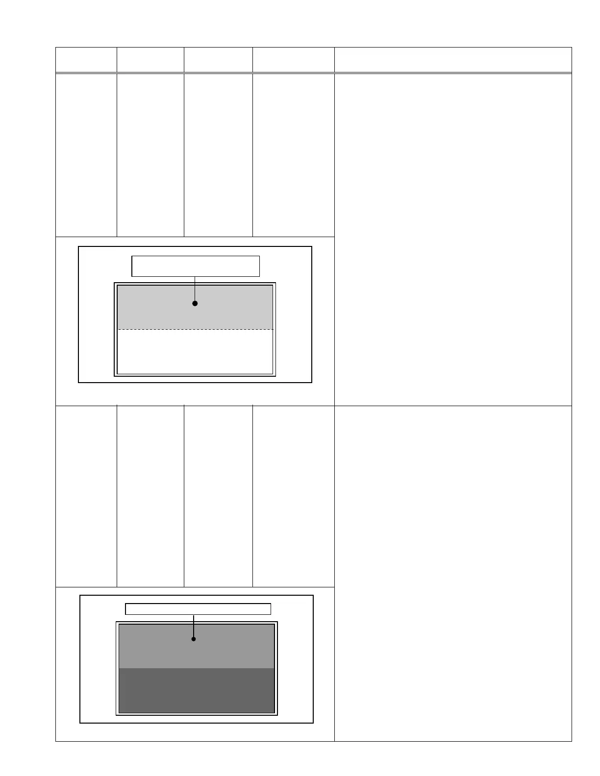
(6) Set < S013 > (1125i blue offset) to minimize the blue
noise in the upper half of the screen. (See Fig.9)
(7) Set < S014 > (1125i red offset) to minimize the red
noise in the upper half of the screen. (See Fig.9)
(8) Readjust < S013 > and < S014 > to set the upper half
of the screen to be the blackest. (See Fig.9)
(9) Set < S001 > to set “000” and it change to the normal
mode.
(10)
Press the [MUTING] key to memorize the set value.
Remote control
unit
Signal generator
Minimize the red and blue noises
in the upper half of the screen.
Fig. 9
RGB
CLAMP LEVEL
[1. ADJUST]
S001:PREPARE
(adjustment setting
mode change)
S020:PC CL LB
(VGA blue clamp
level)
S022:PC CL LR
(VGA red clamp
level)
S030:R DRIVE
(Red drive)
S031:G DRIVE
(Green drive)
S032:B DRIVE
(Blue drive)
(1) Receive a PC (VGA) 0% all-black pattern signal.
(2) Set PICTURE MODE to “STANDARD”.
(3) Select “1.ADFJUST” from the SERVICE MENU.
(4) Set < S030 > (Red drive), < S031 > (Green drive) and
< S032 > (Blue drive) to set “255”.
(5) Set < S001 > (adjustment setting mode change) to
set “020” and it change to the PC (VGA) RGB clamp
level adjustment setting mode.
(6) Set < S020 > (VGA blue clamp level) to set the upper
half of the screen to be the reddest. (See Fig.10)
(7) Set < S022 > (VGA red clamp level) to set the upper
half of the screen to be the bluest. (See Fig.10)
(8) Readjust < S020 > and < S022 > to set the upper half
of the screen to be the blackest. (See Fig.10)
(9) Set < S001 > to set “000” and it change to the normal
mode.
(10)
Press the [MUTING] key to memorize the set value.
Remote control
unit
Signal generator
Blackest in the upper half of the screen
Fig. 10