24
Connection/Installation (TK-C685E/TK-C686E)
Connecting the control signal cable
The maximum connection distance with RM-P2580 is 1,200
m. (Multiple cameras can be connected on one cable for RM-
P2580 but the total length of the cable must be within 1,200
m.)
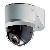
䡵 Connect the cable to the terminal block
A Loosen screws on both sides of the terminal block with a
flathead screwdriver and remove the terminal block as
shown in the diagram below.
Memo :
● Inserting the tip of the screwdriver into the slit of the
terminal block will remove the terminal block easily.
B Peel off about 4 mm of the control signal cable covering
and insert into the terminal.
C Turn the screws on the sides and secure the control
signal cable.
D When the control signal cable is secured, return the
terminal block that was removed in A to its original
position.
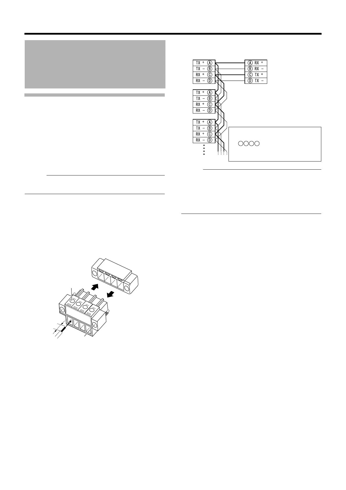
䡵 Overall view of control signal cable connection
Memo :
● We recommend the use of paired cables or twisted pair
cables used in Ethernet rather than 0.61-4-core (2 pairs)
cables.
● Thickness of the cable is R0.4 mm to R1.3 mm.
● Arrange the control signal cables such that the TX+ and
TX–signals and RX+ and RX–signals are pairs.
Cable Connection
(continued)
4 mm
A
A
D
C
Control signal cable
terminal
● To connect correctly, connect
cables that have the same mark
as displayed on the
camera terminal and both
terminals of RM-P2580.
A
B
C
D
Camera terminal 1
Camera terminal 2
amera terminal 3
RM-P2580
TO CAMERA Terminal