JVL Industri Elektronik A/S - User Manual - Ethernet for MAC and MIS motors 23
2.3 Connector description
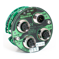
(MAC00-Ex4 continued)
“I/O” - I/O’s and interface. M12 - 8pin female connector.
Signal name Description Pin no.
JVL Cable
WI1000-M12
M8T05N
Isolation
group
(See note)
O1 Output 1 - PNP/Sourcing output 1 White 2
RS232: TX
RS232 interface. Transmit terminal
Leave open if unused.
2 Brown 1
RS232: RX
RS232 interface. Receive terminal
Leave open if unused.
3 Green 1
GND
Interface ground to be used together with the
other signals in this connector. Also ground for
the analogue input (AIN1 - pin 5)
4 Yellow 1
AIN1 Analogue input1 ±10V or used for zero search 5 Grey 1
IN1 Digital input 1 - 12-32V tolerant. 6 Pink 2
IO-
I/O ground to be used with the I/O terminals O1
and IN1.
7 Blue 2
O+
Positive supply input to the output circuitry.
Connect 5-32VDC to this terminal if using the O1
output.
8 Red 2
“L/A IN” - Ethernet port connector - M12 - 4pin female connector “D” coded
Signal name Description Pin no.
JVL Cable
WI1046-
M12M4S05R
Isolation
group
(See note)
Tx0_P Ethernet Transmit channel 0 - positive terminal 1 Brown/White 3
Rx0_P Ethernet Receive channel 0 - positive terminal 2 Blue/White 3
Tx0_N Ethernet Transmit channel 0 - negative terminal 3 Brown 3
Rx0_N Ethernet Receive channel 0 - negative terminal 4 Blue 3
Shield Outside shield connected to connector housing Housing Shield 1
“L/A OUT” - Ethernet port connector. M12 - 4 pin female connector “D” coded
Signal name Description Pin no.
JVL Cable
WI1046-
M12M4S05R
Isolation
group
(see note)
Tx1_P Ethernet Transmit channel 1 - positive terminal 1 Brown/White 4
Rx1_P Ethernet Receive channel 1 - positive terminal 2 Blue/White 4
Tx1_N Ethernet Transmit channel 1 - negative terminal 3 Brown 4
Rx1_N Ethernet Receive channel 1 - negative terminal 4 Blue 4
Shield Outside shield connected to connector housing Housing Shield 1
* Note: Isolation group indicate which terminals/circuits that a galvanic connected to each other. In other
words group 1, 2, 3 and 4 are all fully independently isolated from each other. Group 1 correspond to the hous
-
ing of the motor which may also be connected to earth via the DC or AC input supply.