40 JVL Industri Elektronik A/S - User Manual - Ethernet for MAC and MIS motors
3.3 Commisioning
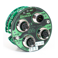
3.3.1 Indicator LED’s - description.
The LED's are used for indicating states and faults of the Ethernet. There is one power
LED, two link/activity LED's (one for each Ethernet connector), and 2 status LED's.
LED indicator descriptions - Covers both MAC and MIS/MIL.
LED Text
MAC/ MIx
Colour Constant
off
Constant
on
Blinking Single flash Double flash Flickering
L/A IN /
L2
Green
No valid
Ethernet
connection.
Ethernet
is
connected.
- - -
Activity on
line
L/A OUT /
L3
Green
No valid
Ethernet
connection.
Ethernet
is
connected.
- - -
Activity on
line
RUN /
L1
Green
Device
state = INIT
Device state
= Opera-
tional
Device
state = Pre-
operational
Device state =
Safe-opera
-
tional
- -
ERROR /
ERR
Red No error
Critical com-
munication
or controller
error
General
configura
-
tion error
Local error
Process data
watchdog
timeout /
EtherCAT®
watchdog
timeout
Booting
error
PWR /
PWR
Green
Power is
not applied.
Power is ap-
plied to both
motor and
module.
- - -
Power is
applied to
module but
no communi
-
cation with
motor.
Notes:
Blinking: Flashing with equal on and off periods of 200ms (2.5Hz). Single flash: Repeating on for 200ms and
off for 1s. Double flash: Two flashes with a period of 200ms followed by 1s off period. Flickering: Rapid flash
-
ing with a period of approx. 50ms (10 Hz).
TT3010-02GB
Error indicator
Hardware serial number
Hardware serial number
General status
indicator
MAC Module Indicators
and label overview
MIS Motor Indicators
and label overview
MAC address
Line activity
indicators
Error indicator
Power indicator
Line activity indicator (CN2)
Line activity indicator (CN3)