JVL Industri Elektronik A/S - User Manual - Ethernet for MAC and MIS motors 93
4.4 Commissioning
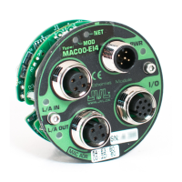
4.4.2 Indicator LED’s - description.
The LED's are used for indicating states and faults of module. There is one power LED,
two link/activity LED's (one for each Ethernet connector), and 2 status LED's.
LED indicator descriptions - Covers both MAC and MIS/MIL.
LED Text
MAC / MIx
Colour Constant
off
Constant
on
(Green)
Blinking
(Green)
Constant
on
(Red)
Blinking
(Red)
Blinking
(Red/
Green)
Flickering
L/A IN /
L2
Green
No valid
Ethernet
connection.
Ethernet is
connected.
- - - - Activity on line
L/A OUT /
L3
Green
No valid
Ethernet
connection.
Ethernet is
connected.
- - - - Activity on line
MOD /
L1
Red/
Green
No power
applied
Module sta-
tus OK
Module not
configured
Major
module fault
Minor
module
fault
Self test in
progress
-
NET /
ERR
Red/
Green
No IP
address
CIP conec-
tion estab-
lished
No CIP
connection
Duplicate IP
address
Connec-
tion time-
out
Self test in
progress
-
PWR Green
Power is not
applied.
Power is
applied.
- - - -
Power is applied
to module but no
communication
with motor
Notes:
Blinking: Flashing with equal on and off periods of 200ms (2.5Hz). Flickering: Rapid flashing with a period
of approximately. 50ms (10 Hz).
TT3043-02GB
Hardware serial number
MAC Module Indicators
and label overview
MIS Motor Indicators
and label overview
Line activity
indicators
Power indicator
MODule status indicator
Line activity indicator (CN2)
Line activity indicator (CN3)
NETwork status
indicator
MODule status
indicator
Power
indicator
Hardware serial number
MAC address