37
F. INSTALLING OPTIONAL K-I-L KEY OR BEST
REMOVABLE CORE OVERRIDE AND OUTSIDE LEVER
Important: Assemble the lever, cylinder and lock components before affixing
the entire unit to the door.
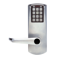
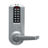
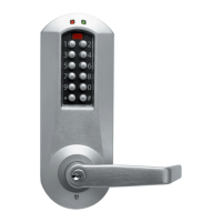
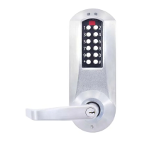
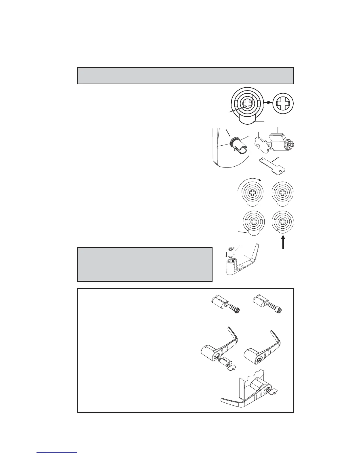
F-1 Upon unpacking, the lock housing with mechanical
override should look like the diagram below with:
• The small indents (i) on the cross of the
override shaft (m) in line horizontally
• The plastic washer (c) on the drive tube
• The lever catch (f) in the out position
• Cylinder (j) and 2 keys (n) (included in the
hardware bag)
• Shaft override tool (o) (included in the
hardware bag)
F-2 Using the override shaft tool (o), turn the override
shaft clockwise until it stops so that the two small
indents on the cross are now vertically in line.
F-3 Push in the lever catch (f) firmly.
F-4 Insert the cylinder (j) into the lever handle (h).
Note: For Best Removable Core, use Steps F-5,
F-6 and F-7, then proceed to F-10 and continue.
For Optional K-I-L Key, skip ahead to F-8 and
proceed as normal.
For Best Removable Core
F-5 Insert 6-pin Best adapter (thicker) into
6-pin interchangeable core or insert
7-pin Best adapter (thinner) into 7-
pin interchangeable core. Insert the
adapter until it makes contact with
the removable core.
F-6 Using the control key, assemble the
removable core with its adapter into
the lever. Remove control key.
F-7 Insert the change key into the removable
core.
f
7-pin
adapter
Thinner
adapter
Thicker
6-pin
(j
)
(o
)
h
j
(f)
(i)
(m)
(c, d)
(n)