Page 24
INSTALLATION GUIDE - REMOTE ACCESS CONTROLLER RAC 4XT • PK3191_10_14
6.0 Annex B Peripheral Wiring Diagrams
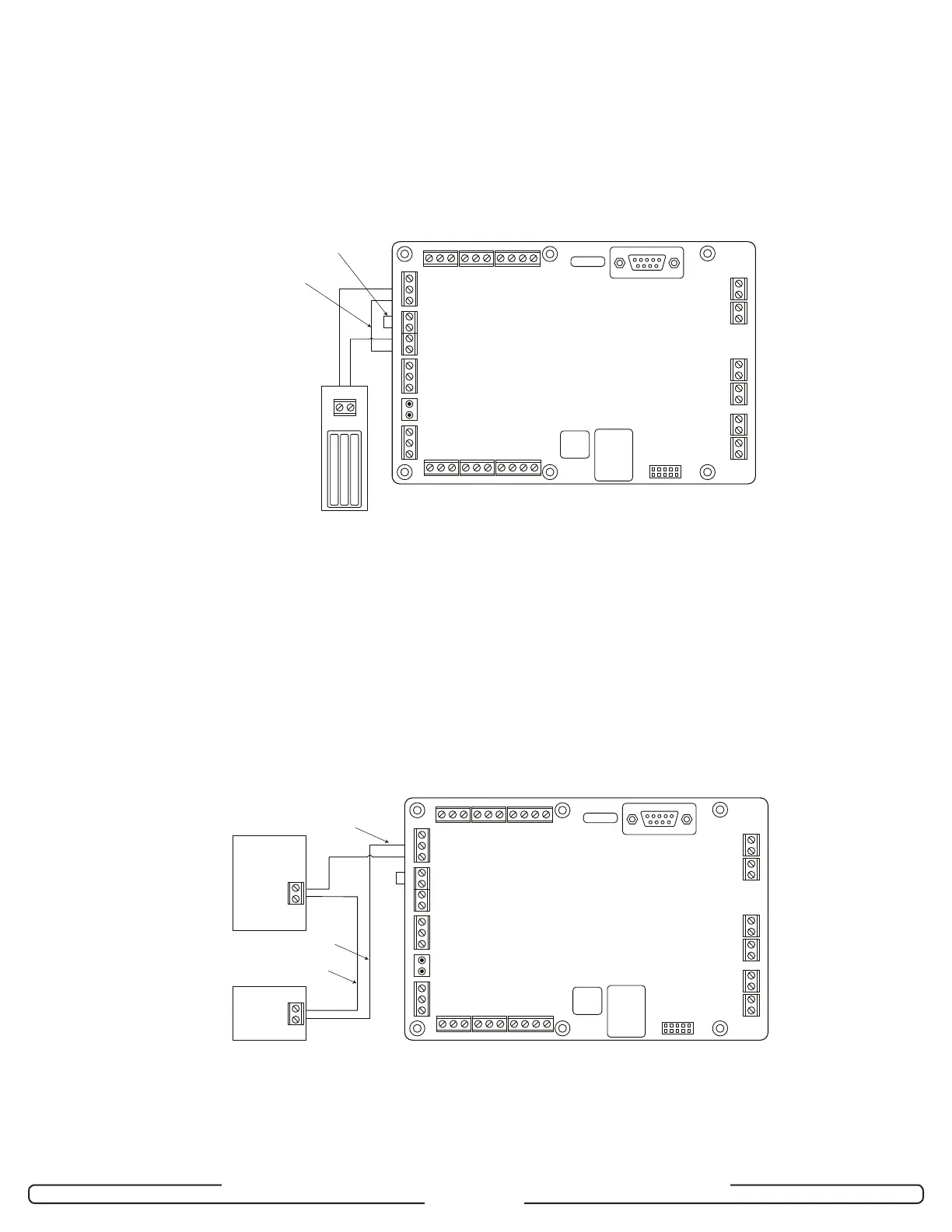
Note: To automatically unlock the door in case of fire, remove the Fire Alarm
Bypass wire and connect J18 to the Fire Alarm panel as per Fire Alarm
Panel Wiring diagram (see Annex B, Figure 10).
In this case the Electromagnetic Lock MUST be powered from the
RAC 4XT’s +12V output as shown in this diagram.
+12 V Supply
For Locking Device
Fire Alarm
Bypass Wire
(see Note)
RAC 4XT PCB
5V
NO
5V GND 12V 1 2 3 1 2 3 4
NC COM GND FIRE GND COMNCNO12VGNDLBAT
12V GND
Mag Lock
ACFGND12V
GND
J1
J15
J14 J13 J12
J16 J17 J18 J19
J2 J3
12V 1 2 3
1 2 31
1 2 3
1 2 3 1 2 3 1 2 3 4
1 2 3 1 23 41 21 2 3
2 3
1 2 3 4
1 2 3 4
GNDDOORGNDTPRGNDREXGNDREM CGNDTXRXGND
J8 J7 J6
1 2 3 4 1 2 3 4 1 2 3 4
Locking Device
Supply
+12V (or +24V)
GND
GND 12V
(or 24V)
Ground
External Power
Supply
Output
Voltage
Locking
Device
Note 1: If the locking device is inductive (such as a strike) place a diode across
the locking device’s terminals as shown in the strike wiring diagrams.
Note 2:
See Note 2:
Dependent on locking device type, may connect to Normally Open (NO) or
Normally Closed (NC)
IMPORTANT: Kaba does not provide Technical or Field Support on 3
rd
party locking devices. Please contact the device
manufacturer for assistance on installation or functional issues.
RAC 4XT PCB
5V
NO
5V GND 12V 1 2 3 1 2 3 4
NC COM GND FIRE GND COMNCNO12VGNDLBATACFGND12V
GND
J1
J15
J14 J13 J12
J16 J17 J18 J19
J2 J3
12V 1 2 3
1 2 31
1 2 3
1 2 3 1 2 3 1 2 3 4
1 2 3 1 23 41 21 2 3
2 3
1 2 3 4
1 2 3 4
GNDDOORGNDTPRGNDREXGNDREM CGNDTXRXGND
J8 J7 J6
1 2 3 4 1 2 3 4 1 2 3 4
Figure 7: Externally Powered Locking Device Wiring (+12 volts or + 24 volts)
Figure 6: Electromagnetic Lock Wiring