Page 51 KACO blueplanet 3.0 NX3 M2 KACO blueplanet 5.0 NX3 M2 KACO blueplanet 8.0 NX3 M2 KACO blueplanet 10.0 NX3 M2
KACO blueplanet 15.0 NX3 M2 KACO blueplanet 20.0 NX3 M2
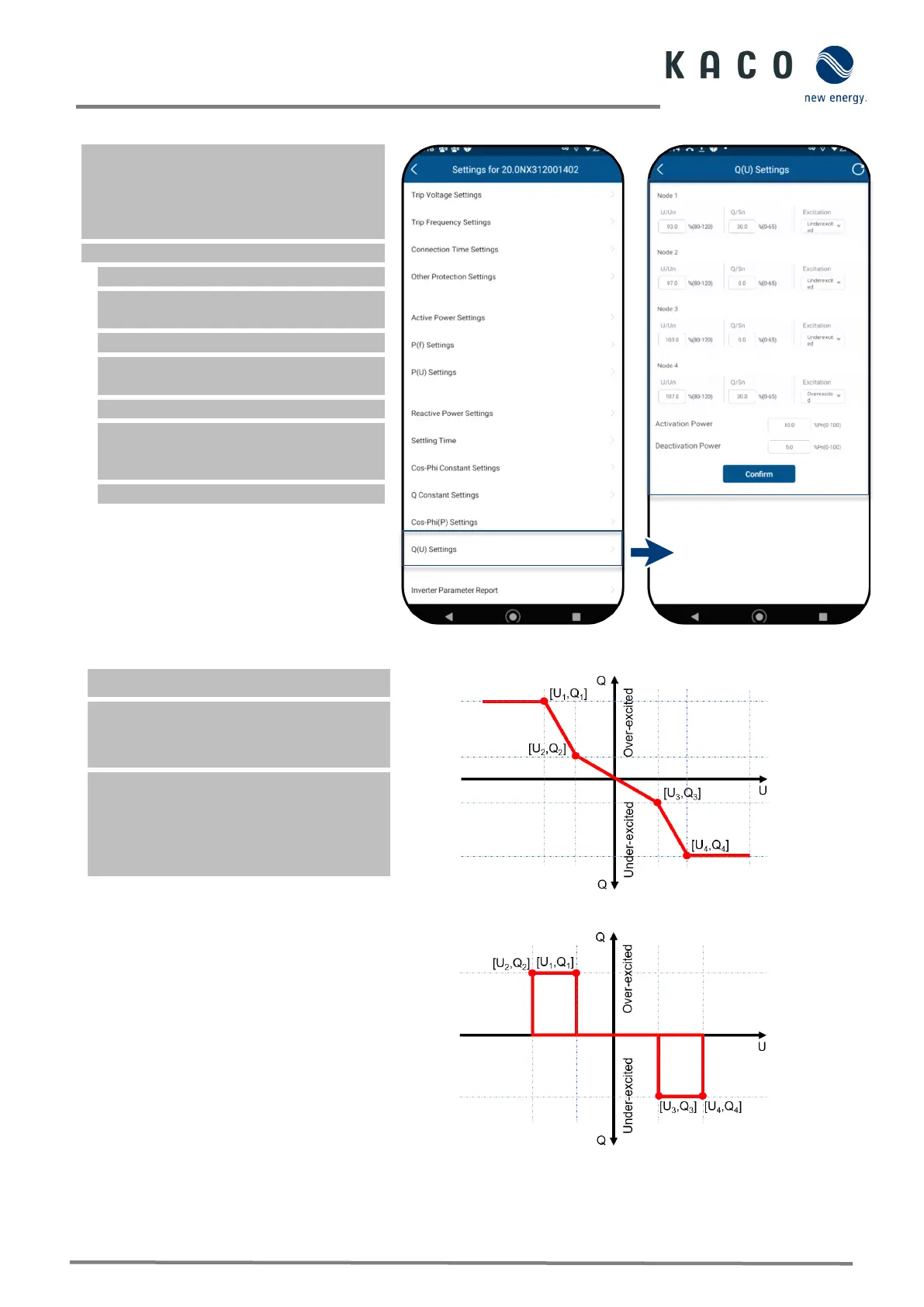
9.12.13 Q(U) settings
Note: Voltage-dependent control Q(U)
regulates the reactive power output
depending on the voltage.
4 coordinates can be set in order to map the
The <Settings for> menu is opened.
1. Select the <Q(U) settings>.
2. Define U/Un, Q/Sn and phase for each
of the 4 coordinates.
3. Set the <Activation power> in % of Pn.
Note: Activation threshold as a percentage
of Pn corresponds to the “Lock-In” voltage.
3. Set the <Deactivation power> in % of Pn.
Note: Deactivation threshold as a
percentage of Pn corresponds to the
Fig. 127. Select Set Q(U) settings
Fig. 128. Set the Q(U) parameters
Definition:
The coordinates are the voltage as a
percentage of Un and the reactive power as a
percentage of Pn.
A grid operator can specify two active power
thresholds as a percentage of Un to activate
or deactivate the function. The active power
thresholds are normally referred to as the
“Lock-In” and the “Lock-Out” active power.
Fig. 129. Q(U) curve and non-hysteresis
Fig. 130. Q(U) curve and hysteresis
 Loading...