MULTICAL® 21 & flowIQ® 2101 /..02 /..03 TECHNICAL DESCRIPTION
Kamstrup A/S •Technical Description • 5512-897_J1_GB • 06.2016 61
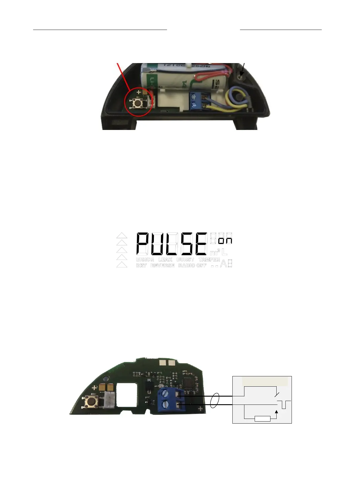
As soon as the button is activated, serial optical communication between Pulse Adapter and meter starts.
If the setup is successful, ‘PULSE ON’ displays for five seconds (as shown below) and the LED on the unit
remains ‘on’ for three seconds – shown in the figure below.
It takes only a very short time from setup starts until it is completed.
Display, after set-up
Having set up the meter, remount the cover on the Pulse Adapter and fasten the three screws.
13.5 Pull-up
The acquisition unit must have built-in ’pull-up’ – shown in figure below – to ensure correct voltage level of
the pulse. The pulse output is two-wired and must be connected as follows:
Opsamlingsenhed
+
-
2
Pull-up
Sketch for connection of Pulse Adapter