5
411d
Reading
Tel: +44 (0)118 9311188 | Email: info@able.co.uk
Aberdeen
Tel: +44 (0)1224 725999 | Email: ab@able.co.uk
Registered Address
ABLE Instruments & Controls Ltd
Cutbush Park, Danehill, Lower Earley,
Reading, Berkshire, RG6 4UT. UK.
Web
able.co.uk
E-commerce
247able.com
5Kamstrup A/S • 55121739_A3_GB_04.2016
MULTICAL® 403
2 Mounting of temperature sensors
The temperature sensors used for measuring forward and return temperatures respectively,
constitute a matched sensor pair, which must never be separated. Temperat ure sensors are
usually mounted in the calculator from the factory. According to EN 1434/OIML R75 the cable
length must not be changed. Should replacement be necessary, both sensors must be replaced.
The sensor marked with a red sign is to be installed in the flow pipe. The other sensor, marked with
a blue sign, is to be installed in the return pipe. For mounting in the calculator, see the paragraph
”Electrical connection”.
Note: The sensor cables must neither be exposed to jerking nor pulling. Please be aware of this
when binding the cables, and be careful not to pull the binders unnecessarily tight as this
may damage the cables. Please also note that temperature sensors must be mounted from
below in cooling or heat/cooling installations.
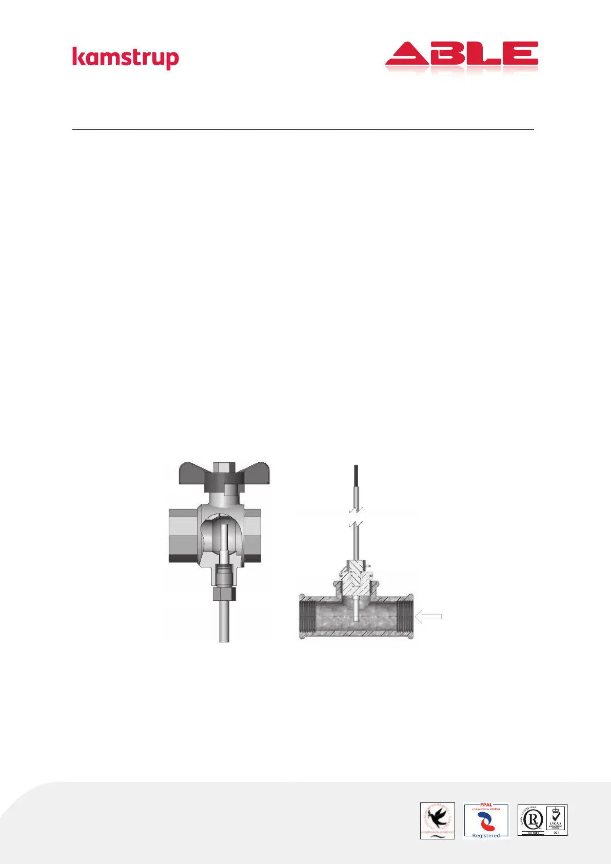
2.1 Direct sensors
The short, direct sensors up to DN25 can be mounted in special ball valves with built-in M 10
socket for the short direct sensor. They can also be mounted in installations with standard angle
tee-pipes. Kamstrup supply R½ and R¾ brass nipples, which fit our short, direct sensor. Make sure
that the tip of the temperature sensor reaches at least the center of the flow pipe. The short direct
sensor can also be direct mounted in all Kamstrup flow sensors with G¾B, G1B, G5/4B and G2
thread on the meter case. Fasten the sensors’ brass unions lightly (approx. 4 Nm) using a 12 mm
face wrench and seal the sensors with seal and locking wire.