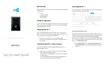
LED Patterns
Visual Status Indicators (LEDs)
The front cover of the KT-1 controller has multiple LED status indicators, which are
used for such activities as troubleshooting, network activity, power status and out-
puts.
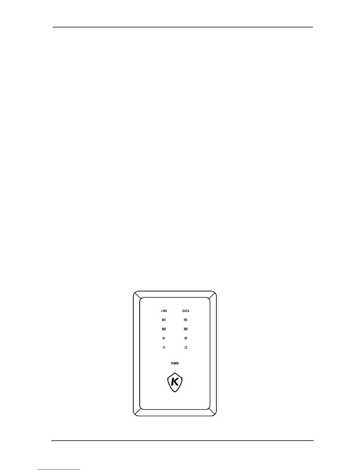
The LED status indicators, as illustrated on the cover diagram below, are as follows:
• LINK (Ethernet): The green LED is OFF when there is no Ethernet network or
the cable is disconnected, and the LED is ON when there is an Ethernet cable
and network connection.
• DATA (Ethernet): The yellow LED indicates network activity.
• RX1 and TX1: The yellow RS-485 serial port LEDs transmit (TX1) and receive
(RX1) activity between the KT-1and the gateway.
• RX2 and TX2: Future use.
• R1 (Relay 1) and R2 (Relay 2): Each output has a red LED indicator which turns
on each time the corresponding relay is activated.
• L1 (Lock 1) and L2 (Lock 2): Each lock output has a red indicator which turns on
each time the corresponding output is activated.
• POWER: The green DC power LED is ON when the DC level is sufficient for all DC
terminals, such as the 12V AUX. For further details, see the Troubleshooting &
Configuration section of this guide.
• Kantech Shield (The One Button): The blue LED indicates the communication
status with EntraPass or the IP mode of the controller.
© Copyright, 2016, all rights reserved
23
 Loading...