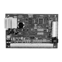
Door Locking Devices
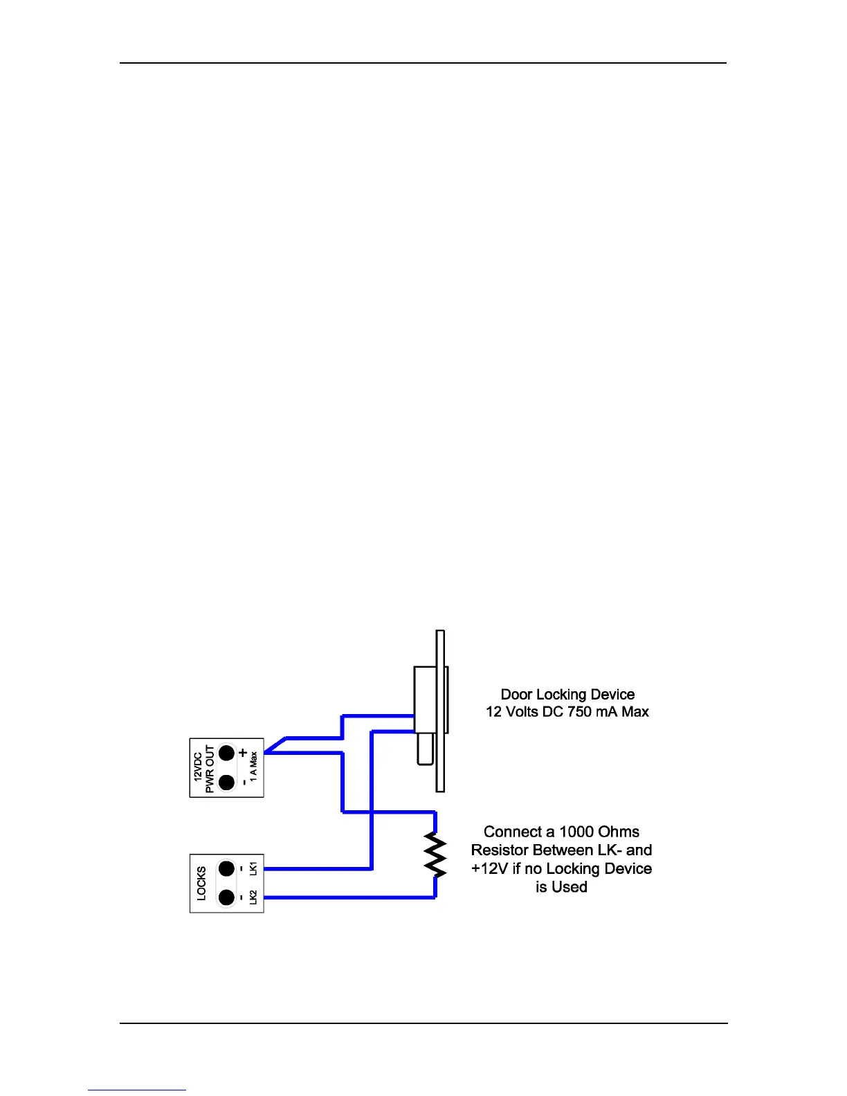
Connect the door lock device to + and LK1- or + and LK2-, if needed. Check for local
“magnetic lock” regulations. The locking device outputs are controlled according to
the end-user programmed parameters for allowing access to or unlocking doors
according to schedules and access levels. These doors locking device outputs can
operate DC powered locking devices such as electromechanical strikes and can be
configured to operate fail-safe or fail-secure (normal or reverse action).
Note: If required, the KT-1 can provide galvanically isolated output(s) by pro-
gramming any of the relays (KT-1-PCB only).
Note: Use 1 K ohm EOL (End-of-Line resistor) between + and LK- terminals if not
used.
To connect the door locking device:
1 - Connect the negative wire from the door strike to the LK1- output, and option-
ally, the door magnetic lock to the LK2- output.
2 - Connect the positive wire to the +12 VDC output.
Lock Set-up for KT-1
©Copyright, 2016, all rights reserved
30
 Loading...