Instructions for use ELECTROmatic M/C and PM/PC
4 Installation | 4.4 Installation position 1: Mount below a holder
34 / 78
CAUTION
Damage to the dentist element.
Installations involving an intervention on the treatment unit might damage
components, which can interfere with the safe function and cause injury.
▶ Have installations involving an intervention on the treatment unit per-
formed by trained expert personnel only.
▶ Have the treatment unit subjected to a safety check after installation.
▶ Use the insert holder as a template for the screw positions on the underside
of a holder. If possible, use existing screws or perforations as screw posi-
tions.
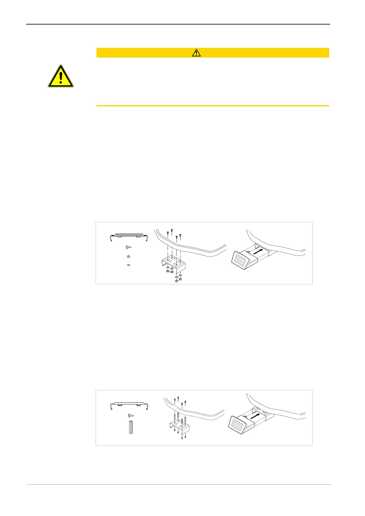
Assembly variant a)
The following parts from the scope of delivery and the installation set are
needed:
▪ 1x Insert holder
▪ 4x Screws M4x12 ④ with self-locking nuts ①
▪ 4x Washers ②
▶ Use 4 screws ④ and 4 washers ② to screw the insert holder to the holder
and fasten it using the 4 nuts ①.
Assembly variant b)
The following parts from the scope of delivery and the installation set are
needed:
▪ 1x Insert holder
▪ 8x Screws M4x12 ④
▪ 4x Spacer bolts, 35 mm ⑦
▶ Use 8 screws to mount the spacer bolts ⑦ or larger commercial spacer bolts
(electronics supplies) between the insert holder and the lower edge of the
holder to increase the distance between the holder and the insert holder, if
applicable.