✓ The name plate data has been compared against the purchase order and the
site data (e.g. supply voltage, frequency, pump operating data, etc).
✓ The fluid to be handled is a permissible fluid. (⇨ Section 4.7 Page 18)
✓ The installation room is frost-proof.
✓ All structural work required has been prepared in accordance with the
dimensions stated in the connection example and in EN 12 056.
✓ The installation room is of sufficient size - see connection example.
✓ The installation room is adequately lit.
✓ Alarm messages are always recognised in time by the operator (use an external
alarm transmitter, if required).
1.
Place the lifting unit on a level floor. Use a spirit level to level the system.
2. Place pads 99-3.2 under the foot areas of tank 591.
3. Use the transport/float protection fixtures supplied to secure the lifting unit
firmly to the floor.
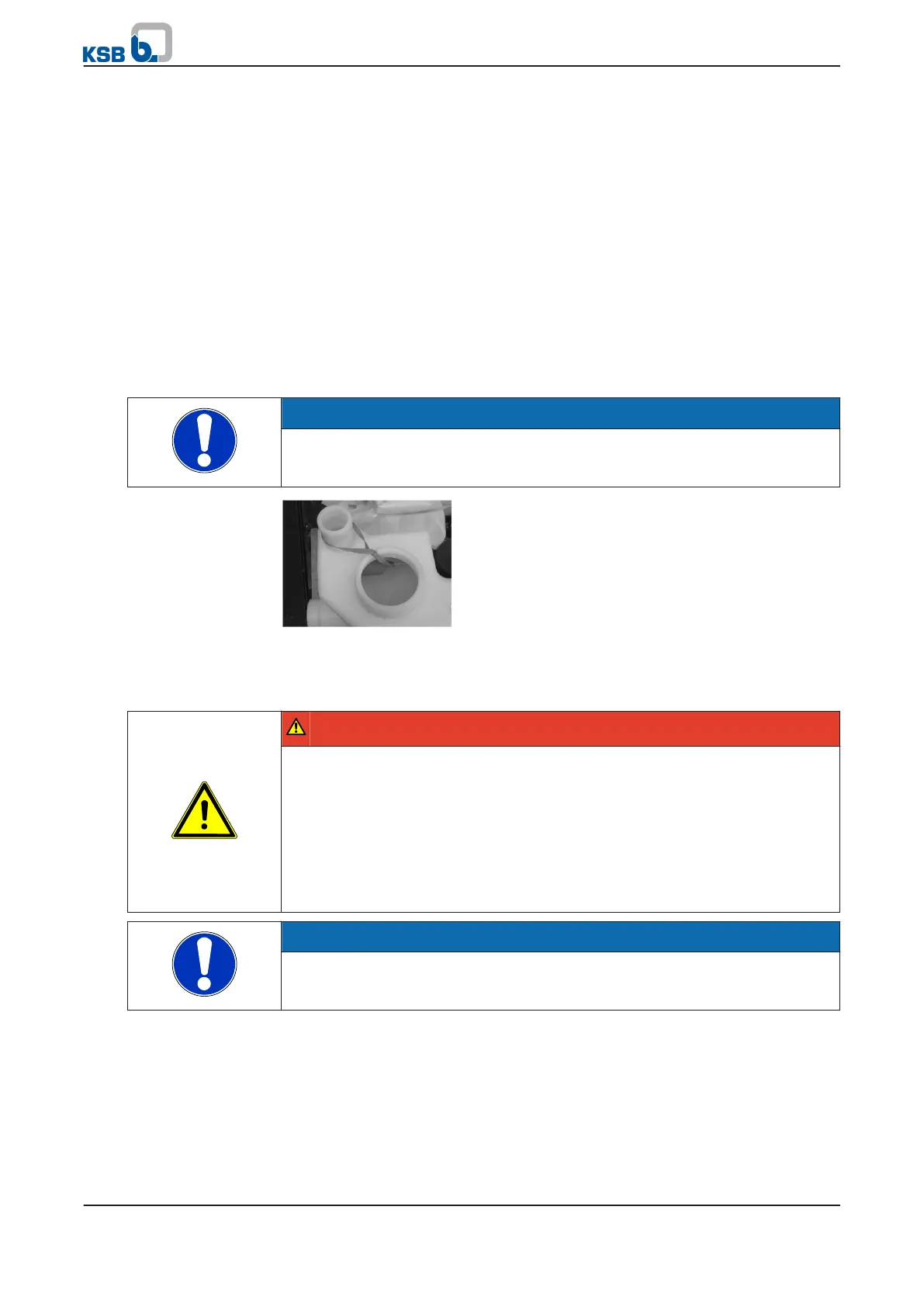
NOTE
To prevent in-transit damage, the level sensor has been fitted with a transport lock
which must be removed prior to commissioning (see Fig.)
Fig. 7: Removing the transport lock
5.4 Connecting the piping
DANGER
Impermissible loads acting on the system nozzles
Danger to life from leakage of hot, toxic, corrosive or flammable fluids!
▷ Do not use the lifting unit as an anchorage point for the piping.
▷ Anchor the pipes immediately upstream of the lifting unit and connect them
without transmitting any stresses or strains.
▷ Observe the permissible forces and moments at the lifting unit. (⇨ Section 8.7
Page 50)
▷ Take appropriate measures to compensate thermal expansion of the piping.
NOTE
The installation of check and shut-off elements is mandatory. However, such
elements must not obstruct proper drainage or hinder disassembly of the lifting
unit.
✓ Piping weights have been supported at the site.
✓ All tank nozzles (except for the vent nozzle) are closed.
1.
Determine which connection nozzles will be used.
2. Open the nozzles required (▼A) by sawing off the nozzle faces (approx. 10 mm).
5 Installation at Site
22 of 86
mini-Compacta