Name Standard
Created
Prep. by
Reviewed
Date
Supersedes
Page
PageAmended
Superseded byOrig.
03
02
01
0
1
23.02.07
Ka
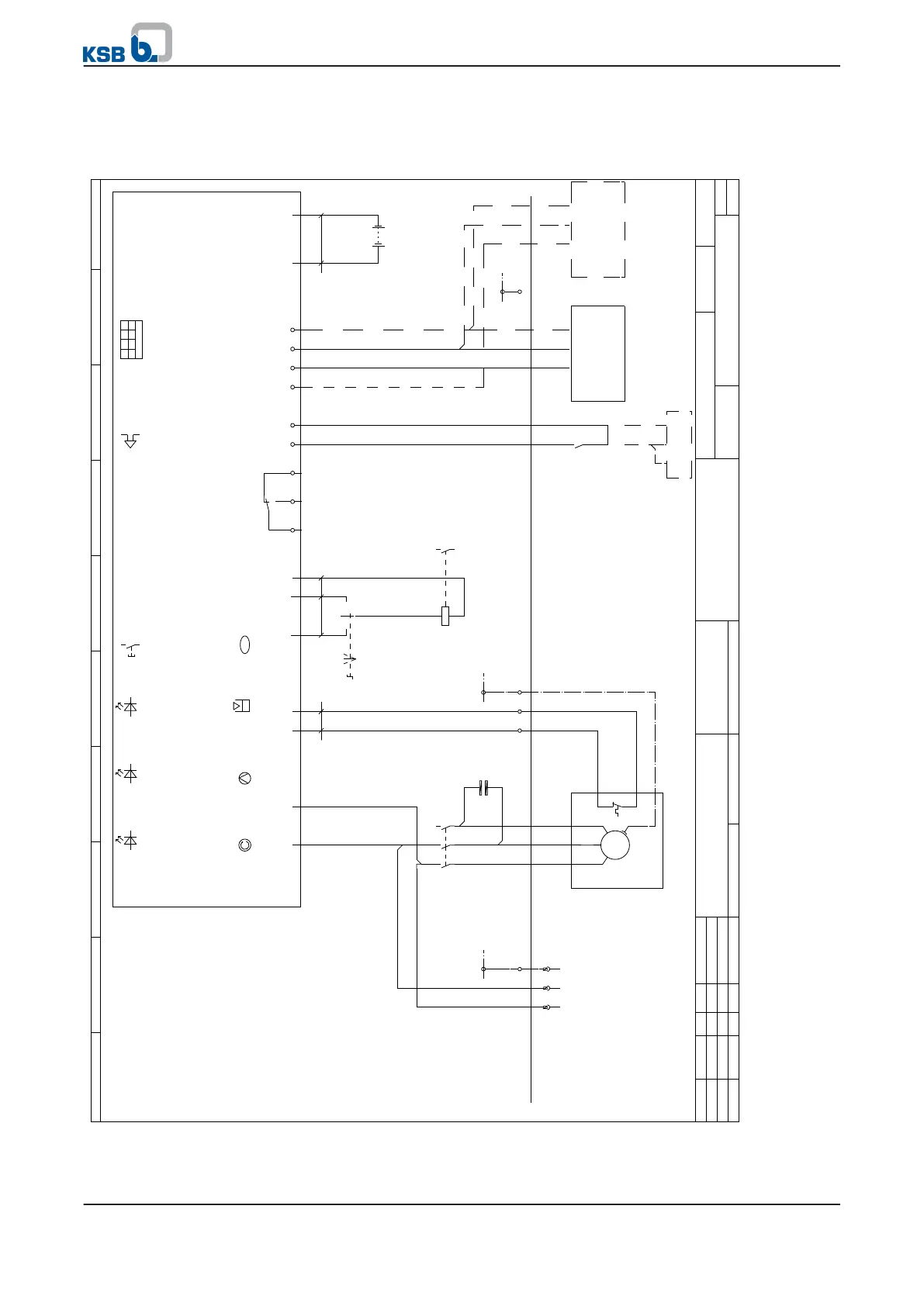
Level Control Basic 1
2 3 4
Anschlussplan
Wiring diagram
Plan de connexion
5 6 7
BD705155
8
= +
9
1
1
Single-phase motor
0.75 kW / 1.5 kW
0.75 kW mutual capacitance 25 ƞF
1.5 kW mutual capacitance 40 ƞF
Limit of scope of supply
Control cabinet
L1
BN
Max. back-up fuse 16 A
Max. connection cross-section 2.5 mm
2
N
BU
Power supply
230V AC/50Hz
PE
X0 PE
PE
GN/YE
Conductor No.
-A1
-M1
L1
-K1
1
2
1
U1
M
~
PE
Rotary field indicatorL2/N
3
4
2
U2
Single-phase motor
L3
5
6
3
Z2
WSK
230 V
-C1
25 ƞF
40 ƞF
Excessive motor
temperature
RD/WH
T1
1
4
High water +
ext. fault
T2
2
5
PE
PE
-S1
A
0
H
.
Acknowledgement
acoustic alarm
ok
MAN
.
RD/WH
1a
Pump ON
1
-K1
A2
A1
AUT
..
1b
24 V~
Option
Moisture monitor
Three-wire connection
13
14
Volt-free message Pump operation
Level Control
Basic 1
Control unit
General fault message
11 14
Optional
12
-S1
1
Max. connection cross-section 1.0 mm
2
Flexible
Ext. fault
12 V
-S1
13
14
1.4
12 V
3
.
Buzzer
DI
DI
2
-S2
5V
Level sensor
V = 6-30 V DC
Signal = 0.3 - 4.7 V
Sensor connection
12 V
BK
12 V
For V_100
Open
1 2 3
4
DIL switch
AI
BN
S
0
BU
0
Settings
see operating instructions
PE
PE
or
BU
-S2
B+
Level sensor
U = 5VDC
BN= Imax: 1mA
Rechargeable
battery
-B1
+ -
BK
5 V
for V_60
Rechargeable
battery
6 V/1.3 Ah
BN
S
B-
BU
0