NOTE
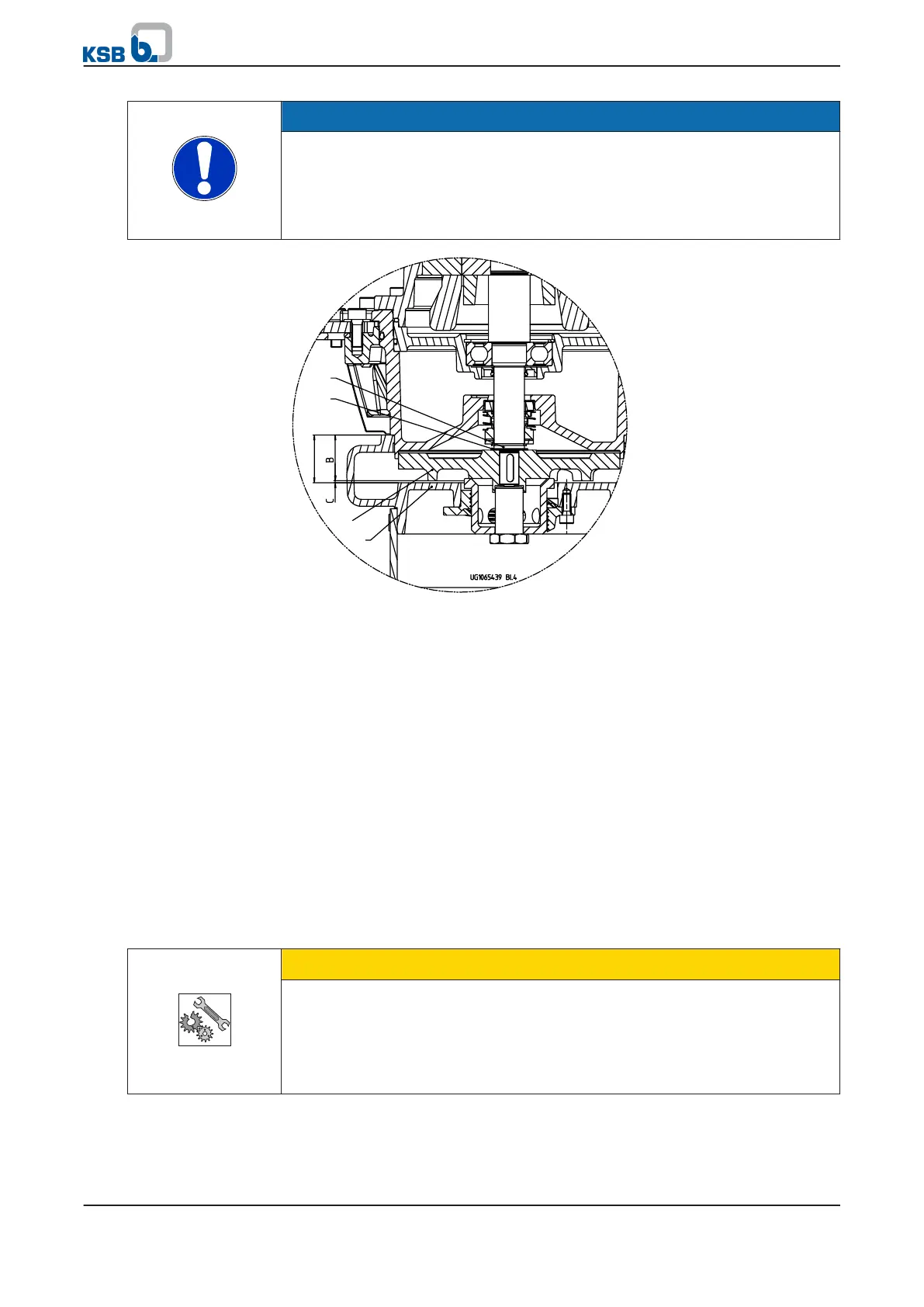
Measure dimension "B" (see Fig. "Checking the impeller clearance").
The impeller clearance "C" results from the difference "A" (= 34.5 mm) - "B".
An impeller clearance of 0.25 to 0.40 mm is required.
If necessary, adjust the clearance by adding adjusting washers 550 (set of adjusting
washers) between impeller 230 and the shoulder of shaft 210. See Fig. "Checking
the impeller clearance".
Fig. 31: Checking the impeller clearance
2.
Mount the rotating assembly on plate 185 using hex. socket head cap screws
914.04 and washers 550.04.
3. Tighten pump casing 100 with studs 902.03, discs 550.03 and nuts 920.03 at
lantern 343 to max. 12 Nm. (⇨ Section 8.7 Page 50)
4. Secure nuts 920.03 with Loctite
®
.
5. After mounting the rotating assembly on the plate, turn the impeller to check
for rubbing noises.
6. Fit rotating assembly 01-44 into casing 100.
8.5 Fitting the level sensor
When reassembling level sensor 81-45 make sure to fit the sensor unit in such a way
that the float cannot get stuck on the tank floor. A residual water level of approx.
50 mm in the collecting tank will prevent this.
8.6 Fitting the repair kit and check valve
CAUTION
Unevenly tightened screws/bolts
O-ring 412.23 will be destroyed!
▷ When tightening the four M8 hex. socket head cap screws 914.21 on the tank,
tighten the screws crosswise, evenly and repeatedly (max. 2 turns) to a torque
of 6 Nm.
Non-compliance may result in leakage and destruction of O-ring 412.23.
8 Servicing/Maintenance
mini-Compacta
49 of 86