87
ANTRIEBSTECHNIK
COMBIVERT F0
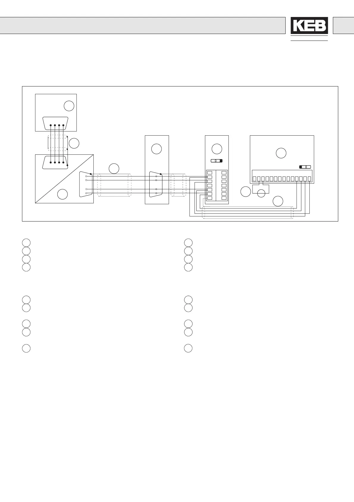
Beispiel für potentialgetrennten Anschluß Example for isolated connection
1 PC mit 9pol. serieller Schnittstelle
2 PC/Interface-Kabel 00.58.025-000C
3 Interface RS232/RS485 00.58.025-0018
4 Busleitung bestehend aus:
– Kabel 2x2x0,22 mm
2
geschirmt 00.90.829-0402
– Stecker 9pol. Sub-D 00.90.501-7712
– Gehäuse für Sub-D-Stecker 00.90.501-7709
5 RS232/485 potentialgetrennt 00.F0.D00-R02Z
6 RS485/OPTOiso-Schnittstelle 00.F0.D00-R20Z
für Rackgeräte
7 Buskabel 00.90.829-0402
8 RS485/OPTOiso-Schnittstelle 00.F0.D00-020Z
für Chassisgeräte
9 Spannungsquelle (nur Chassis)
1 PC with 9-pole serial Interface
2 PC/Interface cable 00.58.025-000C
3 Interface RS232/RS485 00.58.025-0018
4 Bus line consisting of:
– Cable 2x2x0.22 mm
2
shielded 00.90.829-0402
– Connector 9-pole Sub-D 00.90.501-7712
– Housing for Sub-D-Connector 00.90.501-7709
5 RS232/485 isolated 00.F0.D00-R02Z
6 RS485/OPTOiso-Interface 00.F0.D00-R20Z
for rack units
7 Bus cable 00.90.829-0402
8 RS485/OPTOiso-Interface 00.F0.D00-020Z
for chassis units
9 Voltage source (only chassis)
HINWEIS!
Ein potentialgetrennter Anschluß wird in Anlagen eingesetzt, wo
mit unterschiedlichen Bezugspotentialen gegen Masse/Erde zu
rechnen ist (stark belastetes Netz; ausgedehnte bzw. funkentstörte
Anlagen).
Eine Potentialausgleichsleitung kann entfallen, da Ein- und Aus-
gänge der Schnittstellen über Optokoppler galvanisch getrennt
sind.
NOTE!
An isolated connection is used for plants, where different reference
potentials against mass/earth must be taken into account (heavily
loaded power systems: extensive or radio-interference-suppressed
plants).
An equipotential bonding conductor can be omitted, since the
inputs and outputs of the interfaces are galvanically separated by
optocouplers.
CN2
1 8
2 9
3 10
4 11
5 12
6 13
7 14
13579118642 10 121314
+
325
325
RS232
RS485
5 4
89
X3
S1: B
SW1: A
PC
Chassis
Rack
2
4
3
1
7
8
6
COM1
9
7
7
5
4
8
9
X3
Rack
5
RS485 Vollduplex mit Interface
RS485 Full Duplex with Interface
 Loading...


