EasyManua.ls Logo

KEB COMBIVERT R6-N User Manual

KEB COMBIVERT R6-N
160 pages
To Next Page IconTo Next Page
To Previous Page IconTo Previous Page
Page #77 background imageLoading...
Page #77 background image
Digital in- and outputs
© KEB, 2015-07 COMBIVERT R6-N Page3.4 - 7
3
10
Where is the strobe signal come from?
The strobe input is set with parameter di.06. If several inputs are adjusted as strobe, these are OR-connected.
Edge-active or static strobe?
As standard the strobe is slope active, i.e. the input conditions with the rising slope at strobe input are stored
and retained to the next rising slope. In some applications, it is useful to use the strobe in a kind of gate function.
In this case the strobe is static, i.e. the input signals are stored as long as the strobe signal is set (or the gate
is open).
di.07 strobe-mode
di.07: strobe mode
Val-
ue
Function Description
0 edge-active strobe (default)
Input states are stored with the rising edge at strobe input and re-
tained to the next rising edge.
1
static strobe - frooze if
strobe is not active
Input states are updated, as long as the strobe signal is set. When the
signal becomes inactive, the state is retained.
2
static strobe - only active at
active strobe
Input states are updated, as long as the strobe signal is set. When the
signal becomes inactive, the state is reset.
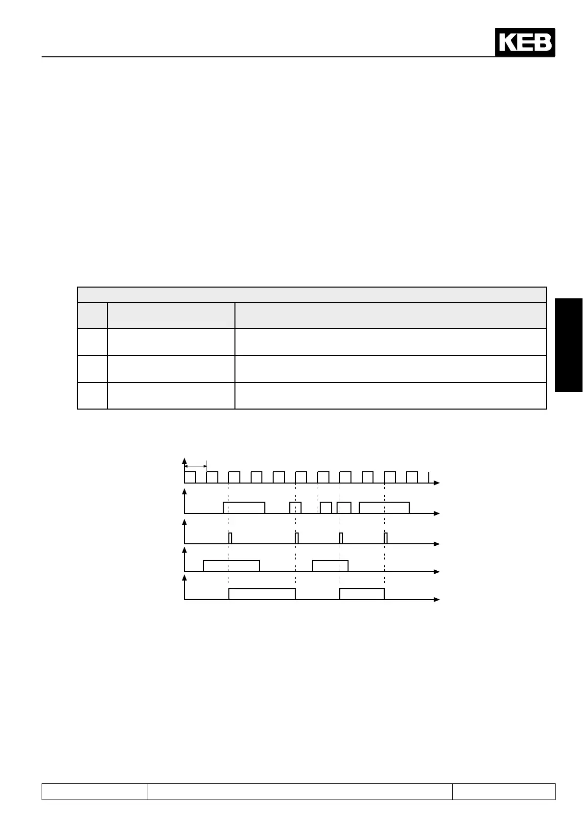
Figure 3.4.8.a Edge active strobe (di.07 = 0)
Scanning grid
(ac-
ceptance upon rising
edge)
t
t
t
t
t
1ms
Strobe input
resulting
strobe signal
Signal at
terminals
Input state
Picture 3.4.8.b Static strobe mode 1 (di.07 = 1)

Table of Contents

Question and Answer IconNeed help?

Do you have a question about the KEB COMBIVERT R6-N and is the answer not in the manual?

KEB COMBIVERT R6-N Specifications

General IconGeneral
CategoryInverter
SeriesCOMBIVERT R6
Protection ClassIP20
TypeR6-N
Input Voltage3 x AC 380...480V
Communication InterfacesCANopen, PROFIBUS, RS485
Cooling MethodAir cooling

Summary

Introduction

Product Overview

Details about the COMBIVERT R6 product, including its features and specifications.

Hardware

Information regarding the physical components and connections of the COMBIVERT R6 unit.

Operation

Fundamentals

Basic principles of operation, parameter handling, and software configuration.

Password Input

Procedures for setting and managing password protection for different operating modes.

Network Components

Overview of available hardware for integrating the COMBIVERT into various network systems.

Functions

Parameter Summary

Comprehensive listing and description of all parameters available for the COMBIVERT R6 unit.

Operating and Appliance Data

Data related to unit operation, including status, voltage, current, and temperature readings.

Analog Outputs

Configuration and function of analog output signals for process variables and PWM signals.

Digital In- and Outputs

Details on configuring and using digital inputs and outputs for control and monitoring.

Regenerative Adjustments

Settings for optimizing the unit's performance in regenerative operation modes.

Protection Functions

Safeguards against overcurrent, overvoltage, and thermal issues.

Parameter Sets

Methods for managing, copying, and selecting different unit configurations.

Special Functions

Advanced functionalities like timers, counters, and master/slave selection.

Define CP-Parameters

Customization of user interface parameters for simplified operation and documentation.

Start-up

Preparatory Measures

Essential steps and checks before powering on and configuring the unit.

Start-up

Procedures for initial setup and operation, covering power supply and regenerative modes.

Error Diagnosis

Troubleshooting

Guidance on identifying, diagnosing, and resolving operational errors and malfunctions.

Error Messages and Their Causes

Detailed list of error codes, their meanings, and potential causes for troubleshooting.

Project Design

General Designs

Guidelines for planning and implementing applications, including control cabinet layout and component dimensioning.

Control Cabinet Design

Schematic and component placement for designing a suitable control cabinet.

Dimensioning Power Supply and Regenerative Units

Criteria for selecting appropriate power supply and regenerative units for system integration.

Appendix

Search and Find

Index and keyword search functionality to locate specific information within the manual.

Related product manuals