Digital in- and outputs
© KEB, 2015-07 COMBIVERT R6-N Page3.4 - 17
3
10
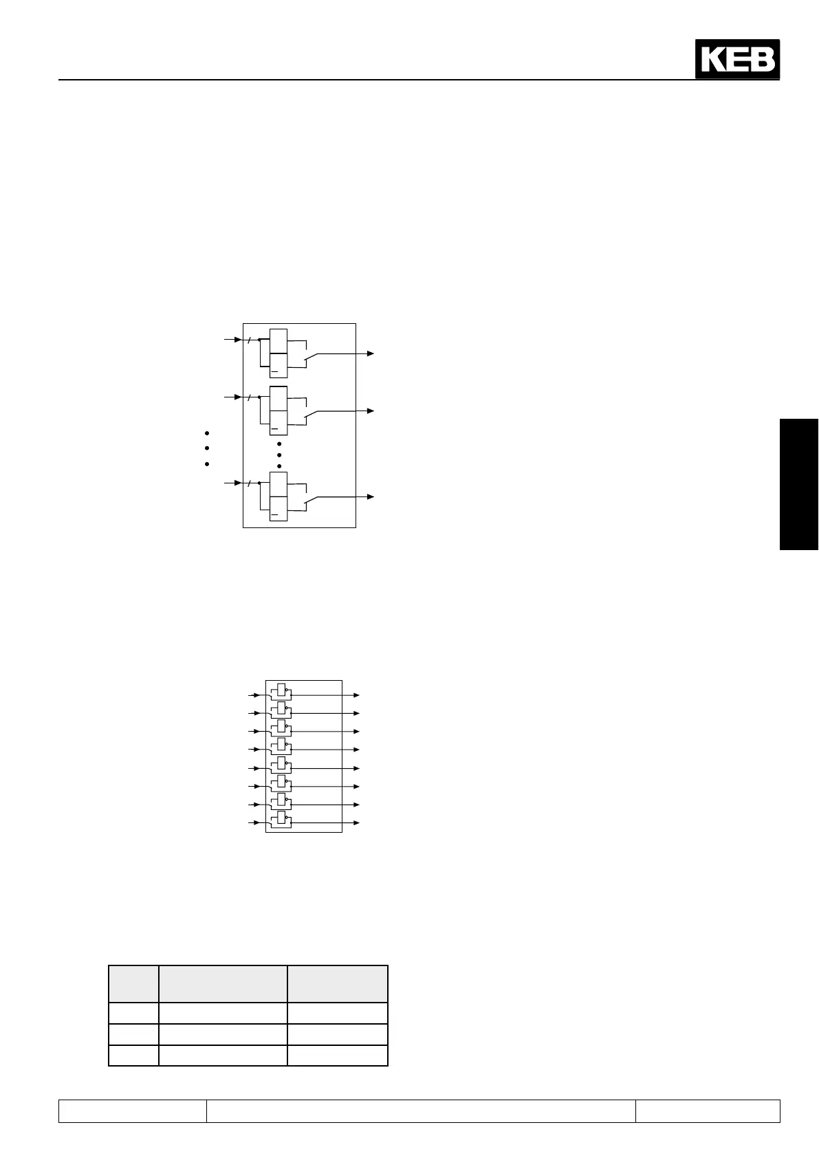
3.4.21Linkingtheags(do.41)
After the switching conditions are selected for each output, it can now be determined, how these are linked. As
adefaultallagsareOR-operated,i.e.ifoneoftheselectedagsismet,theoutputswitches.AnANDconnec-
tion is available as further possibility which can be adjusted with do.41. AND connection means, all selected
agsmustbesetbeforetheoutputswitches.
Picture 3.4.21a. Connecting the outputs
&
>
1
0
1
Bit 0
8
&
>
1
0
1
Bit 1
8
do.34
&
>
1
0
1
Bit 7
8
do.40
do.41
do.33
O1
O2
OD
As shown in picture 3.4.22b. the outputs can be inverted again with parameter do.42 after connection. The
parameter is bit-coded, i.e. according to following table the value belonging to this output must be entered. If
several outputs shall be inverted, the sum is to be formed.
Picture 3.4.21b. Inverting the outputs
1
1
1
1
do.42
Bit 0
Bit 1
Bit 2
Bit 3
Bit 4
Bit 5
Bit 6
Bit 7
1
2
4
8
16
32
64
128
1
1
1
1
do.41
3.4.22 Status digital outputs (ru.25) and digital output state (ru.80)
Parameter ru.25 displays the logic state of the digital outputs after allocation with do.51. Parameter ru.80 indi-
cates the logic condition before the allocation. If an output is set the appropriate decimal value according to the
table below, is output. If several outputs are set, then the sum of the decimal values is output.
Name Function Decimal val-
ues
O1 Transistor output 1
O2 Transistor output 2
R1 Relay output 4

 Loading...