GB - 10
Control
2.3 Connection of the control
Thefollowinginstructionsmustbeobservedatconnection:
Attention Prevent EMC malfunctions
• Use shielded / drilled cables
• Layshieldononesideoftheinverterontoearthpotential
• Installcontrolcablesandpowercablesseparately(approx.10…20cm
distance);KreuzungenimrechtenWinkelverlegen
• To avoid interferences a separate shielding must be provided for analog
and digital control lines. Depending on the use of the relay outputs, an ex-
tra shielding is to be used, too.
• In case of inductive load on the relay outputs a protective wiring must be
provided(e.g.free-wheelingdiode)!
The terminals of the control terminal strip and the transmitter inputs are se-
curely isolated in accordance with EN 50178.
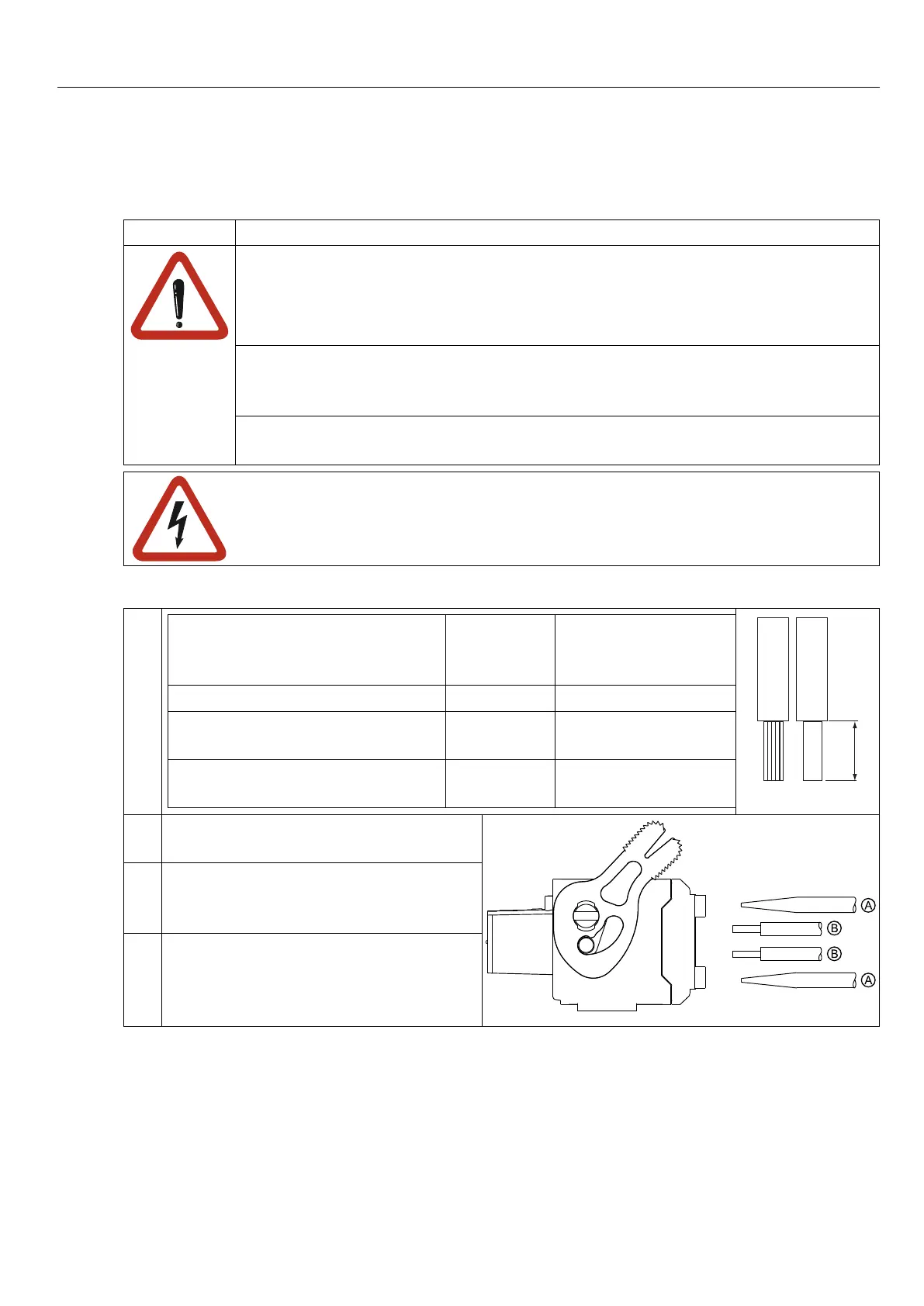
2.3.1 Assembly of the wires
1.
Strandedwirerigidlyandexibly max. perm.
cross-sec-
tion
strippinglengthx=
without wire-end ferrule 1,5 mm² 10 mm
with wire-end ferrule without
plastic collar
1,5 mm² metal ferrule length
with wire-end ferrule with plastic
collar
1 mm² metal ferrule length
+ 2 mm
X
2. Presswithscrewdriver(A)orsome-
thing else onto the labelling
3. Plugstrandedwire(B)intothe
square slot, that no wires can be
seen from the outside.
4. Removescrewdriver(A)andcheck
iftheline(B)isxed.Makesurethat
the stranded wire and not the insula-
tion is clamped.

 Loading...


