GB - 14
Control
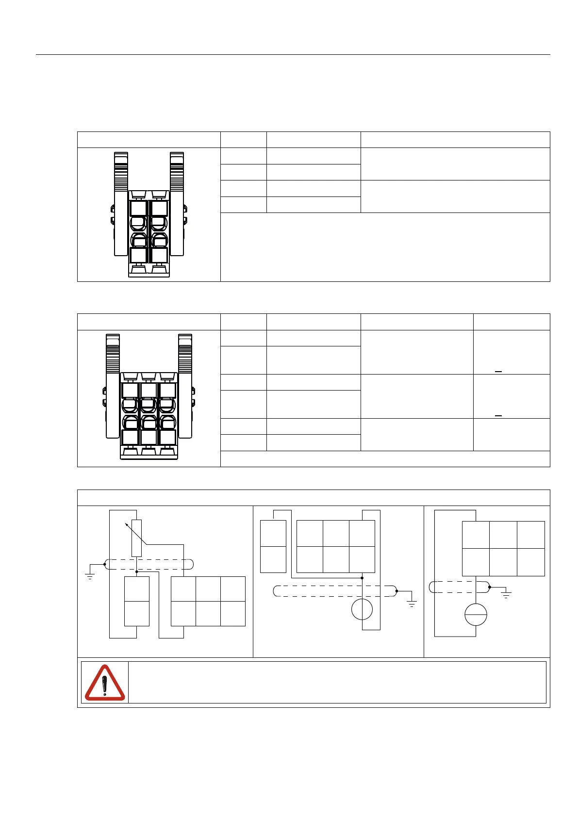
2.6 Assignment of the CAN terminal strip X2C
X2C PIN Name Notes
1
2
3
4
1 CAN low
internally bridged
2 CAN low
3 CAN high
internally bridged
4 CAN high
2.7 Assignment of the terminal strip for analog inputs X2D
X2D PIN Name Notes Specication
1
2
3
4
5
6
1 AN1-
non-oating
differential input 1
±10 Vdc or
4…20mA
0…+20 mA
2 AN1+
3 AN2-
non-oating
differential input 2
±10 Vdc or
4…20mA
0…+20 mA
4 AN2+
5 AN3-
non-oating
differential input 3
±10 Vdc
6 AN3+
2.7.1 Connection of the analog inputs
Examples for the connection of the analog setpoint input
628
5
4
3
2
1
27
R = 0…3/5/10kΩ
4 6
3
2
1
5
28
27
+
*
0…±10Vdc
2
1
4
3
6
5
+
4…20mA
*) Connectpotentialequalizinglineonlyifapotentialdifferenceof>30Vexists
betweenthecontrols.Theinternalresistanceisreducedto30kΩ.

 Loading...


