GB - 13
Control
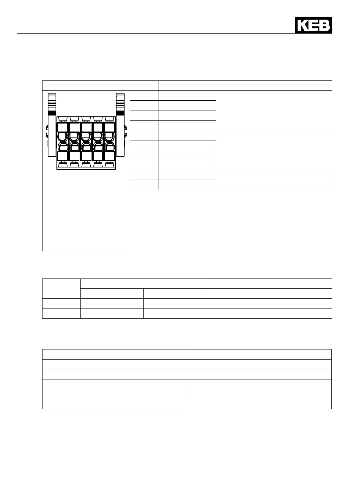
2.5 Assignment of the STO terminal strip X2B
X2B PIN Name I/O
1
2
3 5
6
7
8
9
104
1 STO1+
InputSTOchannel1
2 STO1+
3 STO1-
4 STO1-
5 STO2+
InputSTOchannel2
6 STO2+
7 STO2-
8 STO2-
9 STO-OUT
OutputSTO
10 STO-OUT
The individual channels are designed potential-free, so 24V
and 0 V can be connected. The inputs are designed by way that
safetyswitchgearunitswithtestpulses(OSSDsignals)canbe
connected.Thesignalsarenotevaluated,theyareonlyltered.
TheOSSDtestintervalislimitedto10ms.
ThereferencepotentialforoutputSTO-OUT(terminalsX2B/9
and10)isthemassofthecontrol0V(terminalX2A/26).
2.5.1 Inputs
2.5.1.1 SpecicationoftheSTOinputs
STO
Inputs
Status 0 Status 1
UL[V] IL[mA] UH[V] IH[mA]
max. 5 25 30 25
min. -3 notdened 15 5
The maximum short-term starting current of the input is limited to 300 mA.
2.5.1.2 STOwithOSSDsignals
Theltertimedependsontheminimuminputvoltageandcanbespeciedasfollows:
Inputvoltage[V] OSSDpulsewidth[ms]
15 0.1
18 0.8
20 1.1
24 1.5
30 1.8
2.5.2 Output STO
The short-circuit proof, digital output is specied in accordance with IEC61131-2. The output
rated current is 100 mA at 24 Vdc. The output is 24 Vdc if the inputs STO1 and STO2 are set.

 Loading...


