GB - 11
Control
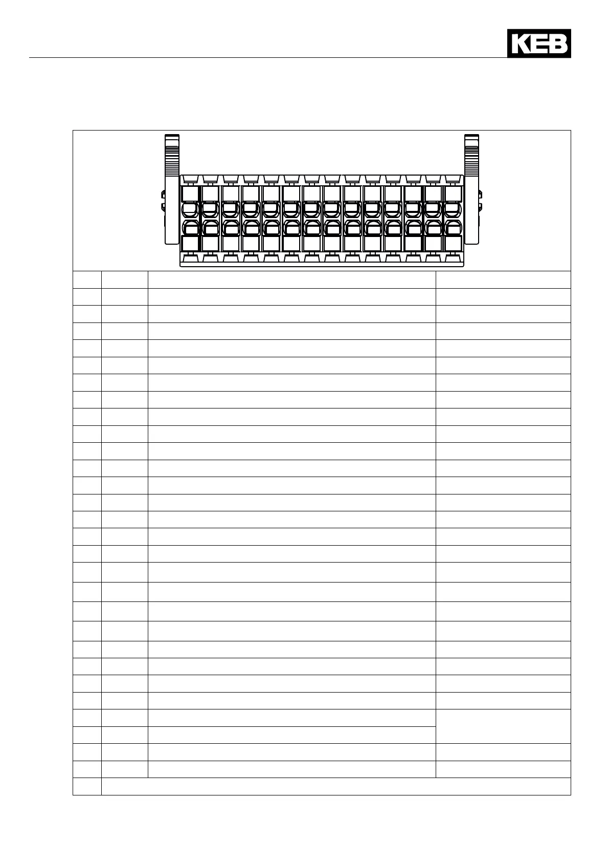
2.4 Assignment of the terminal strip X2A
1
2
3
4
5
6
7
8
9
10
11
12
13
14
15
16
17
18
19
20
21
22
23
24
25
26
27
28
PIN Name Description Specications
1 Out1 Digital output 1 I
max
=100mA
2 0V Reference potential for digital output
3 Out2 Digital output 2 I
max
=100mA
4 0V Reference potential for digital output
5 Out3 Digital output 3 I
max
=100mA
6 0V Reference potential for digital output
7 Out4 Digital output 4 I
max
=100mA
8 0V Reference potential for digital output
9 I1 Digital input 1
10 24V Voltage output for the control of the inputs +24 Vdc*
11 I2 Digital input 2
12 24V Voltage output for the control of the inputs +24 Vdc*
13 I3 Digital input 3
14 24V Voltage output for the control of the inputs +24 Vdc*
15 I4 Digital input 4
16 24V Voltage output for the control of the inputs +24 Vdc*
17 I5 Digital input 5
18 24V Voltage output for the control of the inputs +24 Vdc*
19 I6 Digital input 6
20 24V Voltage output for the control of the inputs +24 Vdc*
21 I7 Digital input 7
22 24V Voltage output for the control of the inputs +24 Vdc*
23 I8 Digital input 8
24 24V Voltage output for the control of the inputs +24 Vdc*
25 24Vin Voltage input for external supply
24 Vdc ± 25 %
26 0V Reference potential for 24Vin
27 CRF 10 V Reference voltage for analog inputs 10 Vdc / I
max
=4mA
28 AGND Analogmass(donotconnectto0V)
*) Totalcurrentofall24Vdcoutputs:100mA

 Loading...


