GB - 26
Safety Function STO
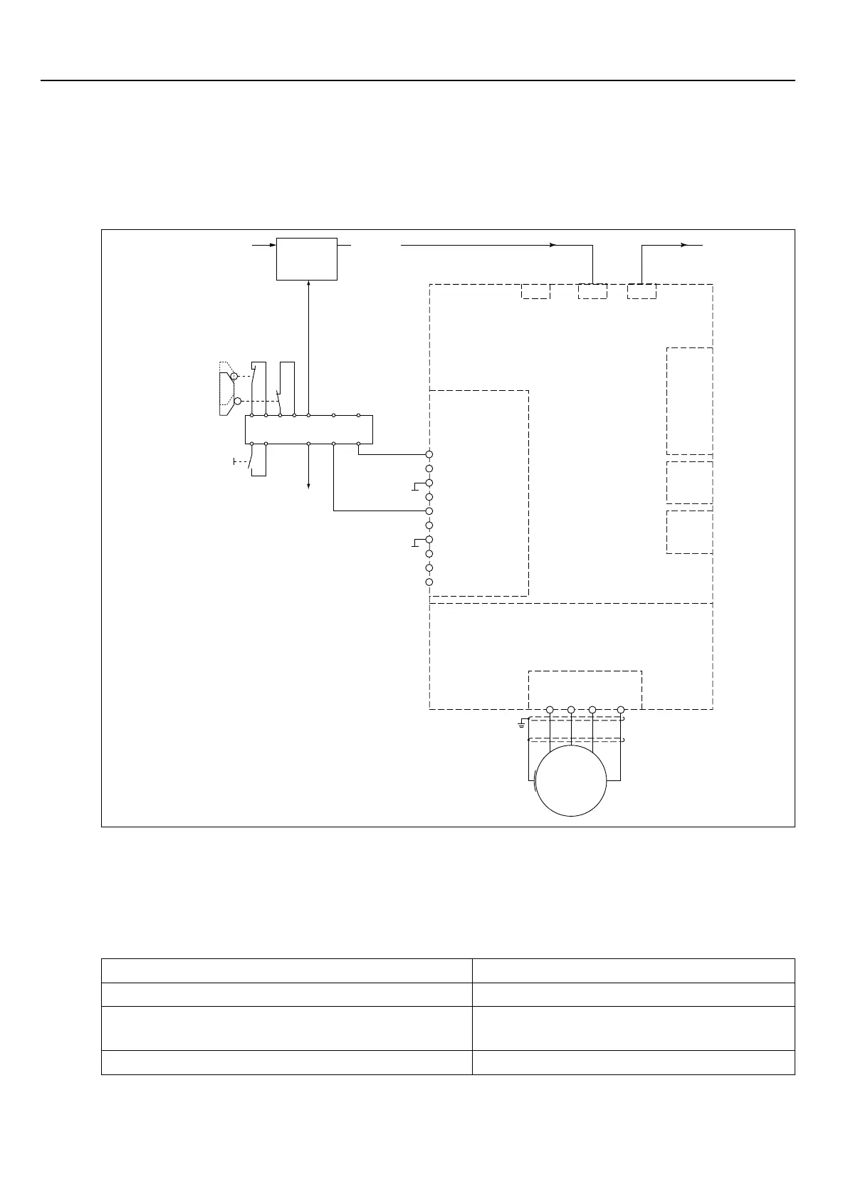
3.6.4 Wiring SS1
AttrippingSS1(SafeStop1)thedriveisonlydisconnectedfromsupplywhenithasreached
astandstill[IEC61800-5-2].Thestopmodeisnotdirectlyrequested,butthemaximumtime
until reaching the standstill is estimated. This period is loaded in a safe time relay, which dis-
connectsthedrivenallyfromsupply.
U V W PE
M
X1A
X4A
Terminal strip X2B
Diagnosis
Power circuit
Control circuit
open
closed
S1 S2
Safety device
Receipt
X2A.13
Safety module
1 - STO1+
2 - STO1+
3 - STO1-
4 - STO1-
5 - STO2+
6 - STO2+
7 - STO2-
8 - STO2-
9 - STO-OUT
10 - STO-OUT
X2A
X2C
X2D
Field bus
Motion
Control
X4B
Field bus
X4C
Field bus
When pressing the emergency stop unit the drive is stopped with a deceleration ramp via
inputX2A.13(I3).
Simultaneously the expiration of the safe time occurs in the safety module. After expiration of
the safe period the control signals STO1+ und STO2+ (X2B.1 and 5) are removed and thus
the energy supply of the drive is disconnected.
Thefollowingadjustmentsmustbedoneinthedrivemoduleforthefunction„drivestop“:
Parameter Adjustment
pn29„prg.errorstop.mode“(Index0x2A1D) 1:dec.ramp->Fault
pn48-59(0x2A30-0x2A3C) Adjustment of the deceleration and jerk
values for the adjusted error reaction
pn30„prog.errorsource“(Index0x2A1E) 4:I3(hereintheexample)

 Loading...


