GB - 18
Control
2.9.1 Encoder interfaces X3A and X3B
Do not plug on/remove en-
coder cable during operation
Toavoidundenedstatesdonotplugon/remove
the encoder cable during operation.
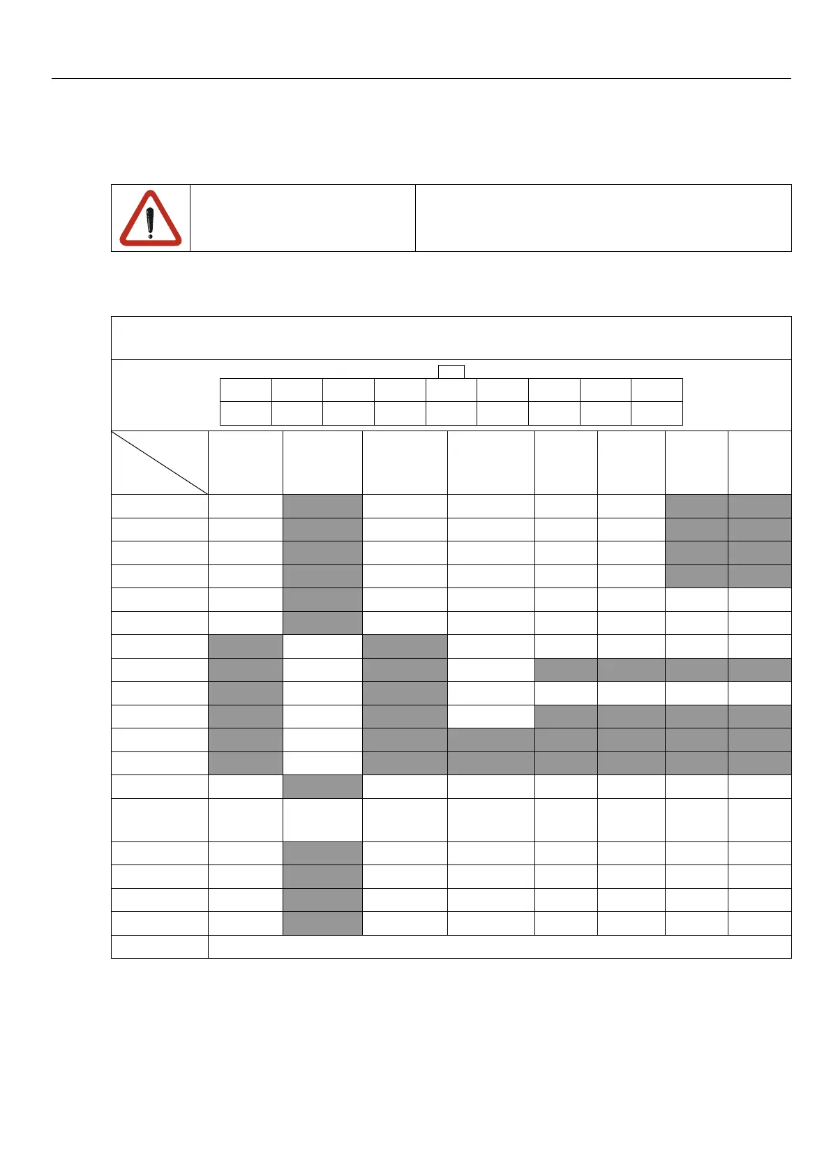
The integrated encoder interfaces are designed for different encoders. The following table
contains the possible encoders and the appropriate signal assignment of the plug connector.
Pin assignment according to the adjusted encoder interface
(frontviewofthecontrol)
2 4 6 8 10 12 14 16 18
1 3 5 7 9 11 13 15 17
encoder
PIN
Inc-TTL Resolver Hiperface SinCos Endat Sin/
Cos-
SSI
Endat
2.2
BiSS
1 A+ COS+ COS+ COS+ COS+
2 A- COS- COS- COS- COS-
3 B+ SIN+ SIN+ SIN+ SIN+
4 B- SIN- SIN- SIN- SIN-
5 N+ Data+ N+ Data+ Data+ Data+ Data+
6 N- Data- N- Data- Data- Data- Data-
7 COS+ Cos_abs+ Clock- Clock- Clock- Clock-
8 COS- Cos_abs-
9 SIN+ Sin_abs+ Clock+ Clock+ Clock+ Clock+
10 SIN- Sin_abs-
11 Exciter+
12 Exciter-
13 COM COM COM COM COM COM COM COM
14 COM
Internal
shielding
COM COM COM COM COM COM
15 8V 8V 8V 8V 8V 8V 8V
16 5.25V 5.25V 5.25V 5.25V 5.25V 5.25V 5.25V
17 24V 24V 24V 24V 24V 24V 24V
18 COM COM COM COM COM COM COM
Shielding open with heat-shrink tube and wire-end ferrule

 Loading...


