CP 503/A, CP 505/A,D,K, CP 507/
A,C
Mounting and installation instructions
Project engineering manual V1.06
31
© KEBA 2021
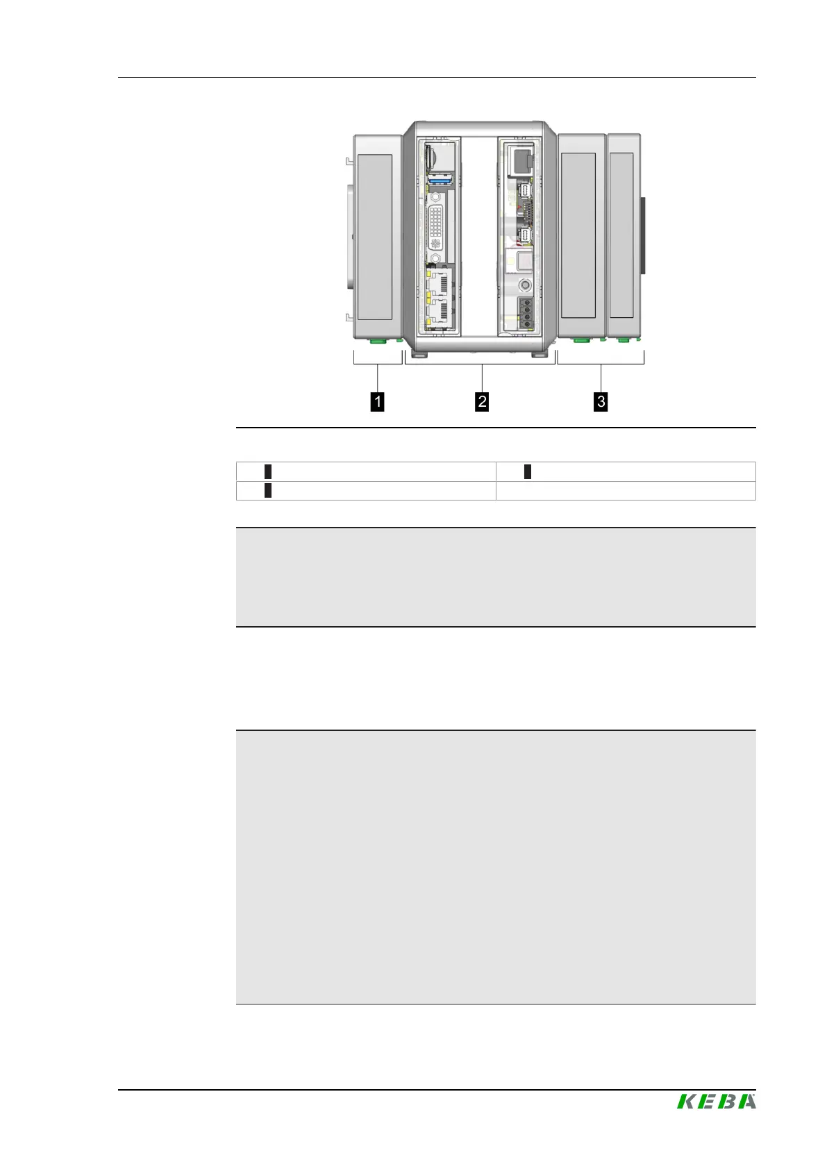
Fig.5-15: Example module package
1 ... Expansion modules 2 ... CP 50x/x
3 ... Input / output modules
Information
For adding and removing input/output modules and expansion modules, the
module package may already be mounted on the mounting rail, see 5.5 In-
stalling the module.
In order to ensure the stable function of the module package, the total power
requirement of the connected modules when added together must not ex-
ceed the performance values of the CP 50x/x specified in the technical data,
see "Technical data".
Information
● In order to calculate the number of input/output modules that can be
connected on the right, the respective performance values specified in
the technical data under "Power input KeBus 5 V" and "Power con-
sumption KeBus 24 V" must be used in the respective configuration
manuals.
● In order to calculate the number of expansion modules that can be
mounted in a row on the left, the power values specified in the technical
data under "Power consumption expansion bus 3.3 V" and "Power con-
sumption expansion bus 24 V" must be used in the respective project
engineering manuals.
● The project engineering manuals of the respective modules must be
taken into account with regard to the order of the expansion modules.
 Loading...