PERFORkfANCE VERfFCA?-ION
4.5 VERIFICATION PROCEDURES
The following paragraphs contain procedures for verify-
ing the one year accuracy specifications of~the in$wnent,
at 5%d resolution, for each of the five measuring !%ncti&w:
DC~volts, TRMS AC volts, ohms, TRMS AC amps, and DC
amps. These procedures are intended for use only by quali-
fied personnel using accurate and reliable test equipment.
If the instrument is out of specifications and not under
warranty, refer to Section 6 for calibration procedures.
WARNING
The maximum common-mode voltage (voltage
between input low and chassis ground) is 500V
peak. Exceeding this value may cause a break-
down in insulation, creating a shock hazard.
Some of the orocedures in this section mav ex-
pose the user to dangerous voltages. Use &an-
dard safety precautions when such dangerous
voltages are encountered.
4.5.1 DC Volts Verification
With the Model 199 set to 5*&d resolution, verify the DC
volts function as follows:
CAUTION
Do not exceed 300V between the input HI and
LO terminals or damage to the instrument may
occur.
1. Select the DCV function and autorange.
~~
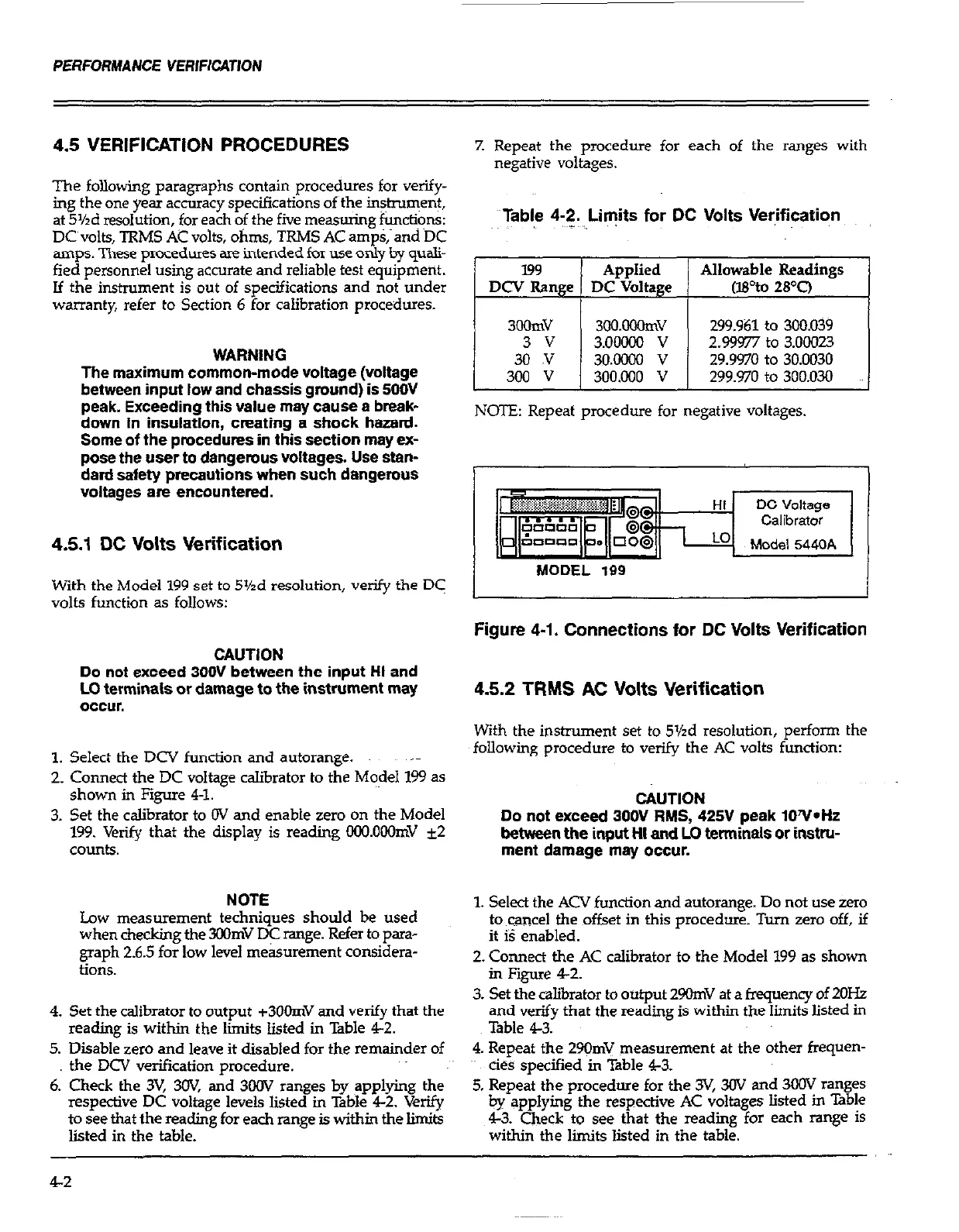
2. Connect the DC voltage calibrator to the Model 199 as
shown in Figure 4-l.
3. Set the calibrator to OV and enable zero on the Model
199. Verifj that the display is reading CGO.OOOmV +2
counts.
NOTE
Low measurement techniques should be used
when checkine the 3oomV DC rawe. Refer to Sara-
graph 2.6.5 forlow level me&ure&ent consihera-
tions.
4. Set the calibrator to output c3OOmV and verify that the
reading is within the limits listed in Table 4-2.
5. Disable zero and leave it disabled for the remainder of
the DCV verification procedure.
6. Check the 3V, 3OV, and 3OOV ranges by applying the
respective DC voltage levels listed in Table 4-2. Verify
to see that the reading for each range is within the limits
listed in the table.
7. Repeat the procedure for each of the ranges with
negative voltages.
datable 4-2. Li@s for DC Volts Ver,ification
Allowable Readings
(IPto 28’0
299.961 to 300.039
2.99977 to 3.00023
29.9970 to 30.0030
299.970 to 300.030
NOTE: Repeat procedure for negative voltages.
MODEL 199
Figure 4-1. Connections for DC Volts Verification
4.5.2 TRMS AC Volts Verification
With the instrument set to 5%d resolution, perform the
following procedure to verify the AC volts function:
CAUTION
Do not exceed 300V RMS, 42%’ peak lOY*Hz
between the input HI and LO terminals or instru-
ment damage may occur.
1. Select the ACV function and autorange. Do not use zero
to cancel the offset in this procedure. Turn zero off, if
it iS enabled.
2. Connect the AC calibrator to the Model 199 as shown
in Figure 4-2.
3. Set the calibrator to output 2-V at a frequency of 2OHz
and verify that the reading is withii the limits listed in
Table 4-3.
4. Repeat the 29omV measurement at the other frequen-
&S specified in Table 4-3.
5. Repeat the procedure for the 3V, 30V and 3COV ranges
by applying the respective AC voltages listed in Table
4-3. Check to see that the reading for each range is
within the limits listed in the table.
4-2