MAINTENANCE
A. With the 30.OOOOmA AC calibration point displayed
on the Model 199, set the current calibrator to out-
put 3O.OOOOmA at a frequency of 5OOHz.
8. After waiting sufficient time for the measurement to
settle, press the NEXT button. The following
message wilJ be displayed for several seconds:
WORKING
C. With the 03.0000mA AC calibration point displayed,
set the current calibrator to output 03.OOOOmA at
5OOHZ.
D. After allowing the measurement to settle, press the
NEXT button. The following message $l be
displayed for several seconds:
WORKING
E. The instrument will exit the calibration program and
retmn to the 3omA range.
F. Repeat the procedures in step 3 for the 3A AC range
using Table 6-9 as a guide.
4. For IEEE-488 bus calibration, proceed as folJows:
A. Set the cunent calibrator tom output 3O.oooOmA at
5OQHz.
8. After allowing sufficient time for the calibrator cur-
rent to settle, send the following command over the
bus: V30E-3XCOX.
C. Set the current calibrator to output 3.ooOOOmA at
5ooHz.
D. After aJlowing sufficient time for the calibrator cur-
rent to settle, send the following command over the
bus: V3E-3XCK Both calibration constants will
automatically be stored in E’PROM.
E. Repeat steps A through D for the remaining ACA
range using Table 6-9 as a guide.
NOTE
After completing the calibration procedure, place
the unit in the “CAL LOCKED” state by pressing
in on the CAL LOCK switch. Also, it is a good idea
to ulace a dated calibration sticker over the switch
access hole.
Table 6-9. TRMS AC Current Calibration
199 ACA
Range
3omA
3 A
Shielded
Cable
I 1
1
-----LO input LO
C”fTe”t m
AC Voltage
Calibrator
Calibrator
Model 2YYJE
Mod4 52COA
HI Input HI
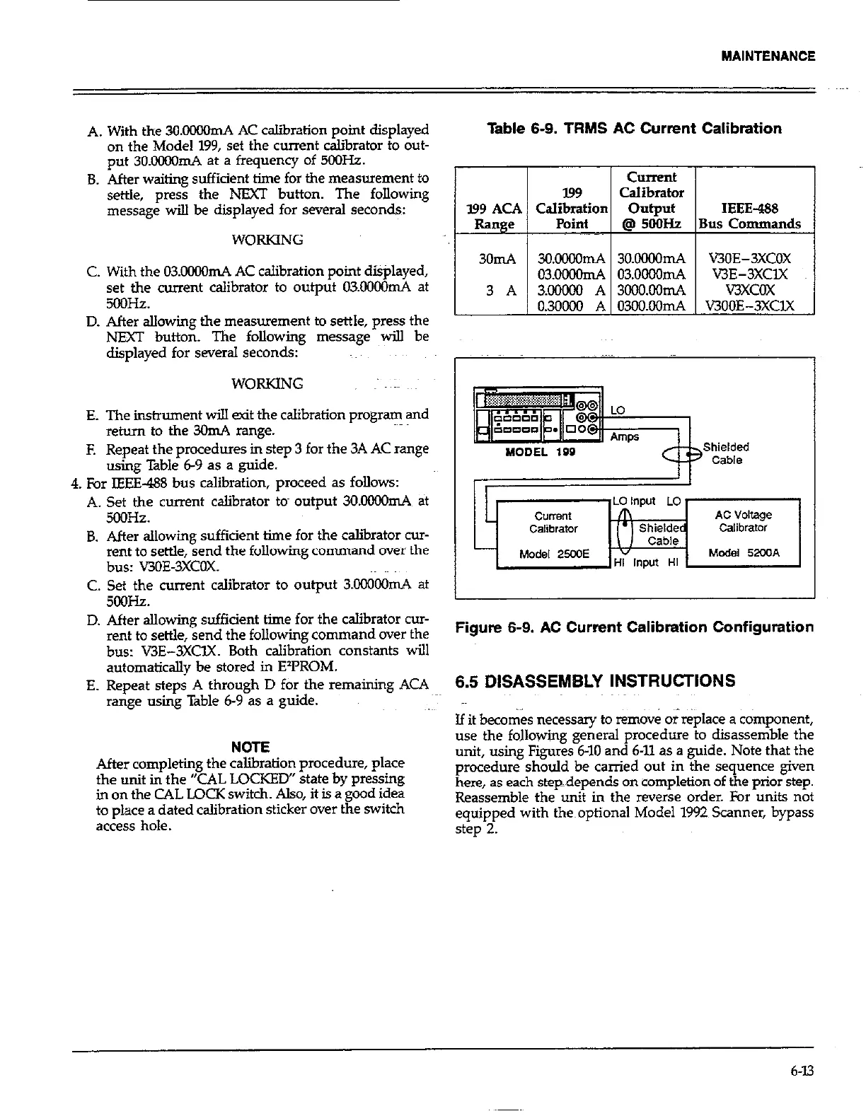
Figure 6-9. AC Current Calibration Configuration
6.5 DISASSEMBLY INSTRUCTIONS
Jf it becor& necessary to rem&e or replace a c&nponent,
use the following general procedure to disassemble the
unit, using Figures 6-10 and 6-11 as a guide. Note that the
procedure should be carried out in the sequence given
here, as each stepdepends on completion of the prior step.
Reassemble the unit in the reverse order. For units not
equipped with the~optional Model 1992 Scanner, bypass
step 2.
6-13