MAINTENANCE
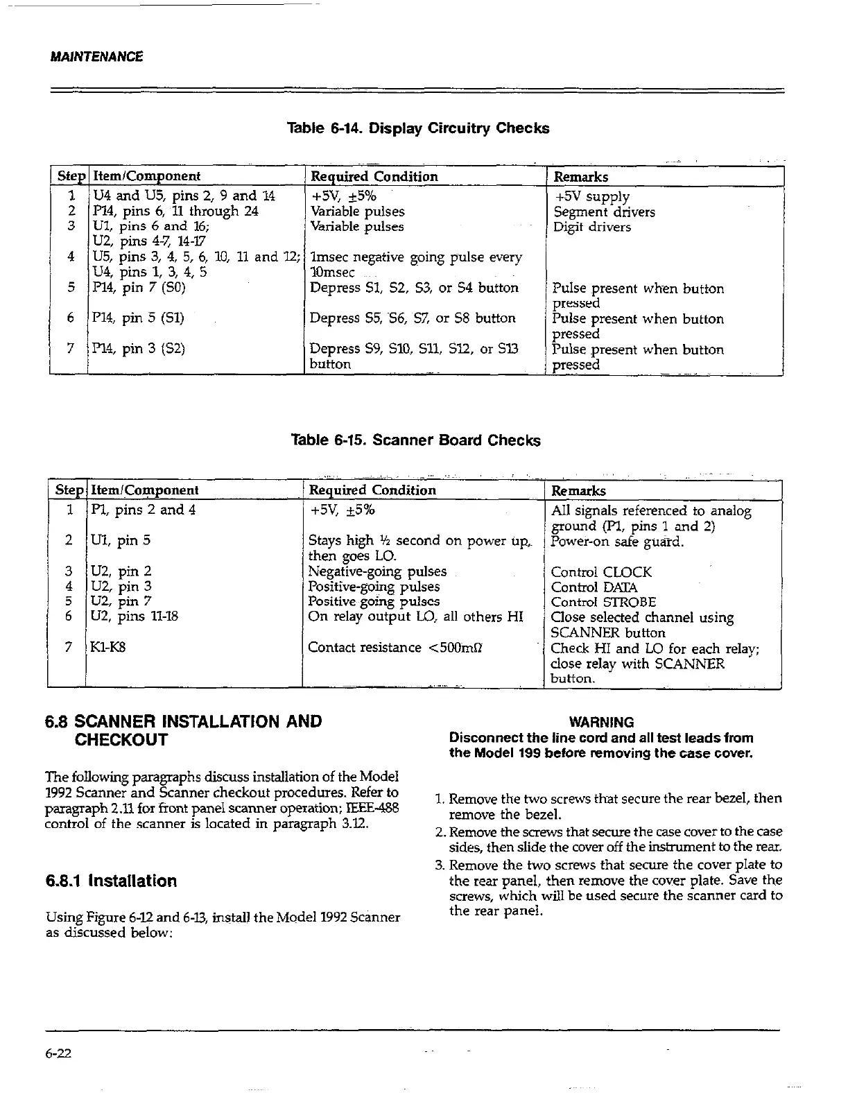
Table 6-14. Display Circuitry Checks
Step Item/Component
Required Condition
1 U4 and US,
pins 2, 9 and 14 +5v, +5%
2 P14, pins 6,
11 through 24 Variable pulses
3 Ul, pins 6 and 16; Variable Dulses
U2, ‘pins 4-7, 14-W
4 U5,
PhS 3, 4, 5, 6,
10, 11 and 12; lmsec negative
going pulse
every
U4,
pins 1, 3, 4, 5 1Omsec
5 P14,
pin 7 (SO)
Depress Sl, 52,
S3, or 54 button
6 P14, pin 5 (Sl)
7 Pl4, pin 3 (S2)
Depress 55, S6, S7, or 58 button
Depress S9, SlO, Sll, Sl2, or Sl3
button
7 KlX8
I I
Table 6-15. Scanner Board Checks
i
i
Stays high Yz second on power up,~
then goes LO.
Negative-going pulses
Positive-going pulses
Positive-going pulses
On relay output LO, all others HI
Contact resistance <5OOtia
Remarks
t5v supply
Segment drivers
Digit drivers
Pulse present when button
pressed
Pulse present when button
pressed
Pulse present when button
e=?sed
Remarks
AI1 signals referenced to analogy’
ground (Pl, pins 1 and 2)
Power-on safe guard.
Control CLOCK
Conhl DATA
Control STROBE
Close selected channel using
SCANNER button
Check HI and LO for each relay;
close relay with SCANNER
button.
6.8 SCANNER INSTALLATION AND
CHECKOUT
The following paragraphs discuss installation of the Model
1992 Scanner and Scanner checkout procedures. Refer to
paragraph 2.11 for front panel scanner operation; lEElZ-488
control of the scanner is located in paragraph 3.32.
Disconnect the line cord and all test leads from
the Model 199 before removing the case cover.
1. Remove the two screws that secure the rear bezel, then
remove the bezel.
2. Remove the mews that seme the case cover to the case
sides, then slide the cover off the instrument to the rear.
3. Remove the two screws that secure the cover plate to
the rem panel, then remove the cover plate. Save the
screws, which will be used secure the scanner card to
the rear panel.
6.8.1 installation
Using Figure 6-12 and 6-U, install the Model 1992 Scanner
as discussed below:
6-22