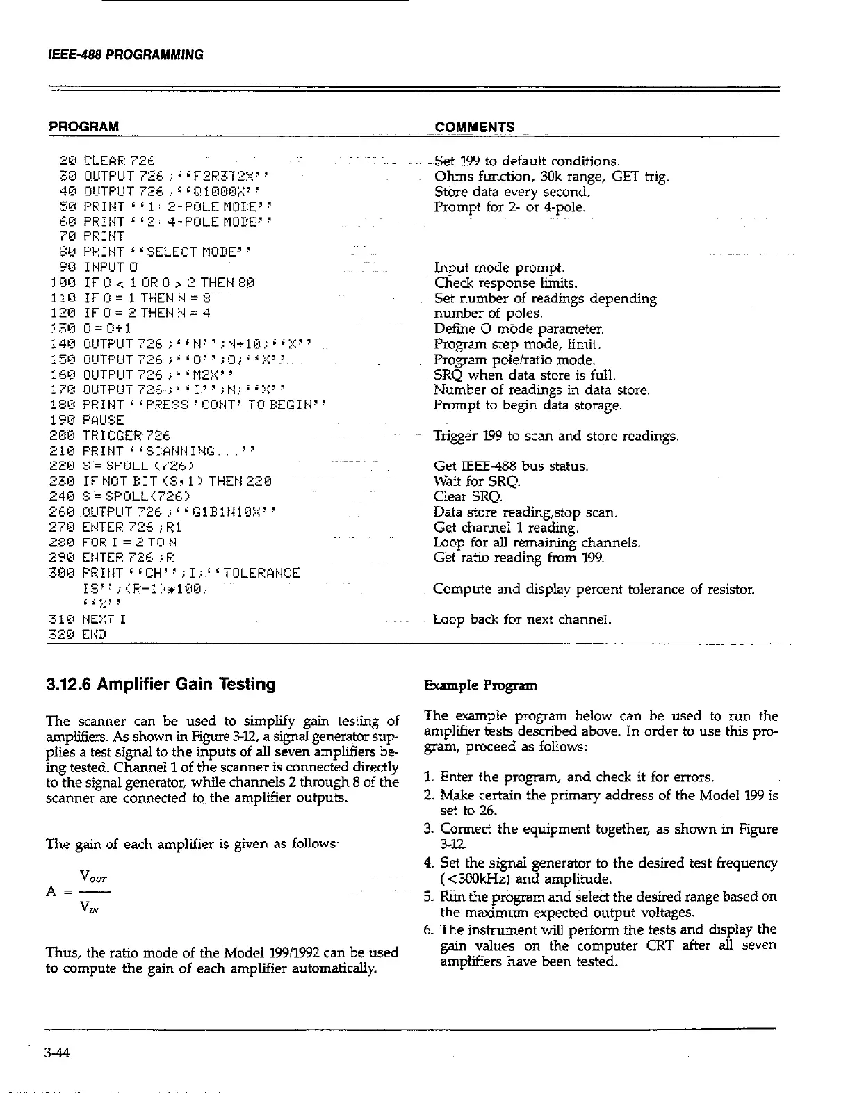
Set 199 to default conditions.
Ohms function, 3Ok range, GET trig.
St&e data every second.
Prompt for z- or 4-pole.
Input mode prompt.
Check response limits.
Set number of readings depending
number of poles.
Defme 0 mode parameter.
Program step mode, limit.
Program pole/ratio mode.
SRQ when data store is full.
Number of readings in data store.
Prompt to begin data storage.
Triger 199 to scan and store readings.
Get IEEE-488 bus status.
Wait for SRQ.
Clear SRQ.~
Data store readmg,stop scan.
Get channel 1 reading.
Loop for all remaining channels.
Get ratio reading from 199.
Compute and display percent tolerance of resistor.
Loop back for next channel.
3.12.6 Amplifier Gain Testing Example Program
The s&%uwr can be used to simplify gain testing of
The ewmple program below can be used to run the gram below can be used to run the
amplifiers. As shown in Figure Z-12, a signal generator sup-
amplifier tests described above. In order to use thii pro- ests described above. In order to use thii pro-
plies a test signal to the inputs of all seven amplifiers be-
1_
gram, proceed as follows: gram, proceed as follows:
ing tested. Channel 1 of the scanner is connected directly
to the signal generator, while channels 2 through 8 of the
1. Enter the program, and check it for errors.
scanner are connected to the amplifier outputs.
2. Make certain the primary address of the Model 199 is
set to 26.
The gain of each amplifier is given as follows:
3. Connect the equipment together, as shown in Figure
342
V
*=2T
VW
4. Set the signal generator to the desired test frequency
(<3CHlkHz) and amplitude.
5. l&n the prbgram and &lea the desired range based on
the maximum expected output voltages.
6. The instrument will perform the tests and display the
Thus, the ratio mode of the Model 19911992 can be used
gain values on the computer CRT after all seven
to compute the gain of each amplifier automatically.
amplifiers have been tested.
3-44