fE&E-488 PROGRAMMING
NOTES:
1. Sending the I command enables data store; however,
the unit must be properly triggered to begin storage once
data store is enabled.
2. When the I command is sent, ‘i-----L’ will be displayed
until the fast trigger occurs.
3. The data store can be disabled by sending the F
command.
4. The INTERVAL OVERRUN error message indicates that
the instrument cannot store readings at~the programm-
ed interval rate. Instead, readings will be stored as fast
as the instrument can run.
5. Either during or after the storage process, readings may
be recalled by using the Bl or B2 command as describ-
ed in the previous paragraph.
Upon power up or after the instrument receives a DCL~
or SDC command, the Model 199 will return to the default
condition.
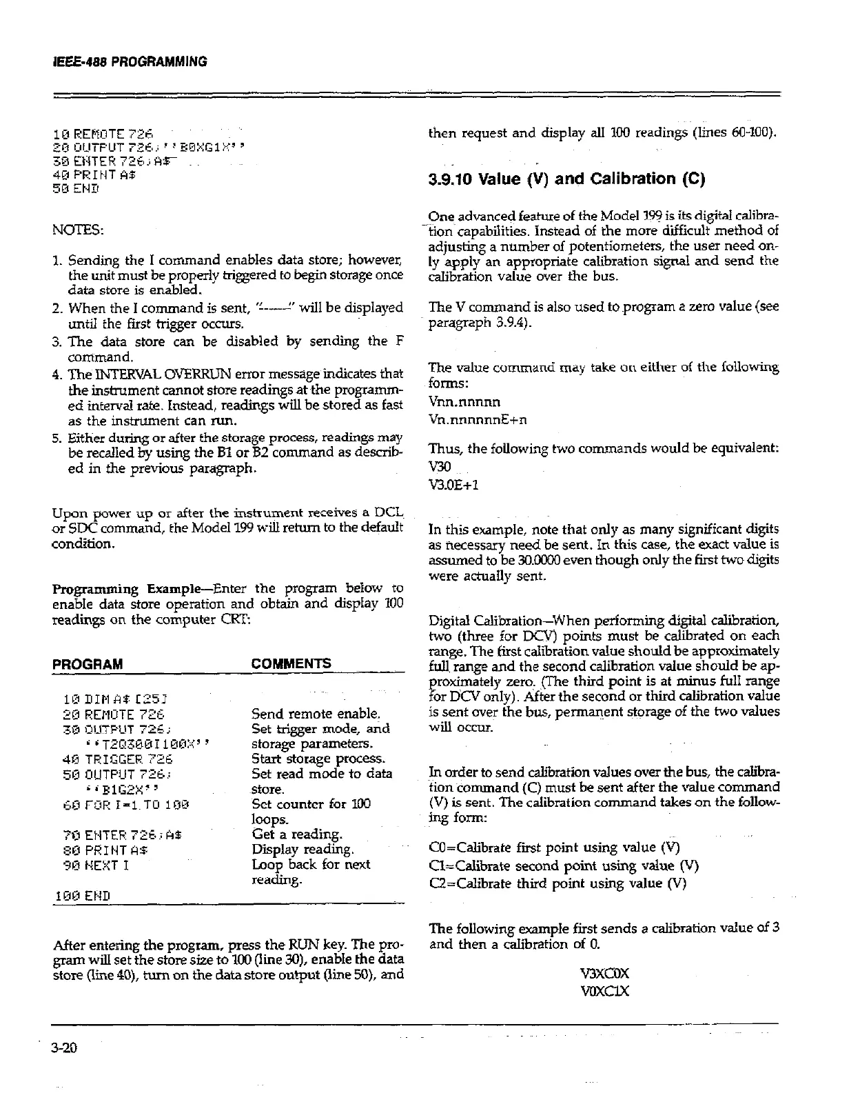
Programming Example-Enter the program below to
enabIe data store operation and obtain and dispIay 100
readiigs on the computer CRT:
PROGRAM
COMMENTS
Send remote enable,
Set trigger mode, and
storage parameters.
start storage process.
Set read mode to data
~siore.
Set counter for Xl0
hp.
Get a reading.
Display reading.
Loop back for next
reading.
After entering the program, press the RUN key. The pro-
gram wilI set the store size to 100 (line Xl), enable the data
store (line 40), turn 011 the data store output (line XI), and
then request and display all 100 readings (lines 60-100).
3.9.10 Value &) and Calibration (C)
One advanced feature of the Model 199 is its digital calibra-
~tion~capabilities. instead of the more diificult method of
adjusting a number of potentiometers, the user need on-
ly apply an appropriate calibration signal and send the
calibration value over the bus.
The V command is also used to program a zero value (see
paragraph 3.9.4).
The value command may take on either of the following
forms:
Vnn.nnnnn
Vn.nnnnnnE+n
Thus, the following two commands would be equivalent:
v30
vAOE+1
In this example, note that only as many significant digits
as necessary need be sent. In this case, the exact value is
assumed to be 3O.COOO even though only the first two digitz
were actually sent.
Digital Calibration-When performing digital calibration,
two (three for DCVj points must be calibrated on each
range. The first calibration value should be approximately
full range and the second calibration value should be ap-
proximately zero. ,(The third point is at minus foul1 range
for DCV only). After the second or third calibration value
is sent over the bus, permanent storage of the two values
will occm.
In order to send calibration values over the bus, the c&bra-
tion command (C) must be sent after the value command
(V) is sent. The calibration command takes an the follow-
ing form:
CO=Calibrate fast point using value (*
Cl=Calibrate second point using value (v)
U=Calibrate third point using value (V)
The following example first sends a calibration value of 3
and then a calibration of 0.
v3xcox
voxclx
3-20