IEEE-488 PROGRAMMING
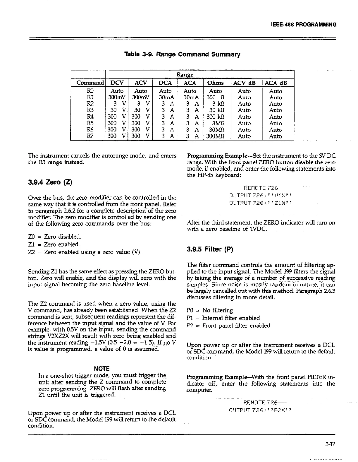
Table 3-9. Range Command Summary
Range
Command DCV ACV DCA 1 ACA 1 Ohms
Auto Auto
Auto Auto Auto
3OOmv 3OOmv 3omA 3omA 300 cl
The instrument cancels the autorange mode, and enters
F’rogramming Example-Se;
the R3 range instead.
range. With the front panel ;
mode, if enabled, and enter
the HP-85 keyboard:
I
R2 1 3 VI 3 VI 3 Al 3 A I 3kO
R3 30 V 30 V
3 A 3 A 30 kQ
R4 300 V 3CO V
3 A 3 A 3LXIkQ
l-6 300 V 300 V
3 A 3 A 3Mi-l
R6 300 V 300 V
3 A 3 A 30MR
I
W 13OOV13OOV/ 3AI iA13OOMQ
3.9.4 Zero (Z)
Ovei the bus, the zero modifier can be controlled in the
same way that it is controlled from the front panel. Refer
to paragraph 2.6.2 for a complete description of the zero
mod9ier. The zero modifier is contmlled by sending one
of the following zero commands over the bus:
ZO = Zero disabled.
ZIP = Zero enabled.
22 = Zero enabled using a zero value (V).
Sending Zl has the same effect as pressing the ZERO but-
ton. Zero will enable, and the display will zero with the
input signal becoming the zero baseline level.
The 72 command is used when a zero value, using the
V command, has already been established. When the 22
command is sent, subsequent readings represent the dif-
ference between the input signal and the value of V. For
example, with 0.5V on the input, sending the command
stings V2XZZ-X will result with zero being enabled and
the instrument reading -19 (0.5 -2.0 = -1.5). If 30 V
is value is programmed, a value of 0 is assumed.
NOTE
In a one-shot trigger mode, you must trigger the
unit after sending the Z command to complete
zero programming. ZERO will flash after sending
Zl until the “nit is triggered.
Upon power up or after the instrument receives a DCL
or SDC command, the Model 199 will return to the default
condition.
T
I
1
-
t tt \e instrument to the 3V DC
ZE: RO button disable the zero
th< e following statements into
\CA dB
Auto
Auto
Auto
Auto
Auto
Auto
Auto
Auto
1
Aft&r the third statement, the ZERO indicator Wi!.l turn on
with a zero baseline of 1VDC.
3.9.5 Filter (P)
The filter command controls the amount of filtering ap-
plied to the input signal. The Model 199 filters the signal
by taking the average of a number of successive reading
samples. Since noise his mostly ran&G inky nature, It can
be largely cancelled out with this method. Paragraph 2.6.3
discusses filtering in more detail.
PO = No filtering
Pl = Internal filter enabled
l’2 = Front panel filter enabled
Upon power up or after the instrument receives a DCL
or SDC command, the Model 199 will return to the default
condition.
Programming Example-With the front panel FILTER in-
dicator off, enter the following statements into the
computer.
347