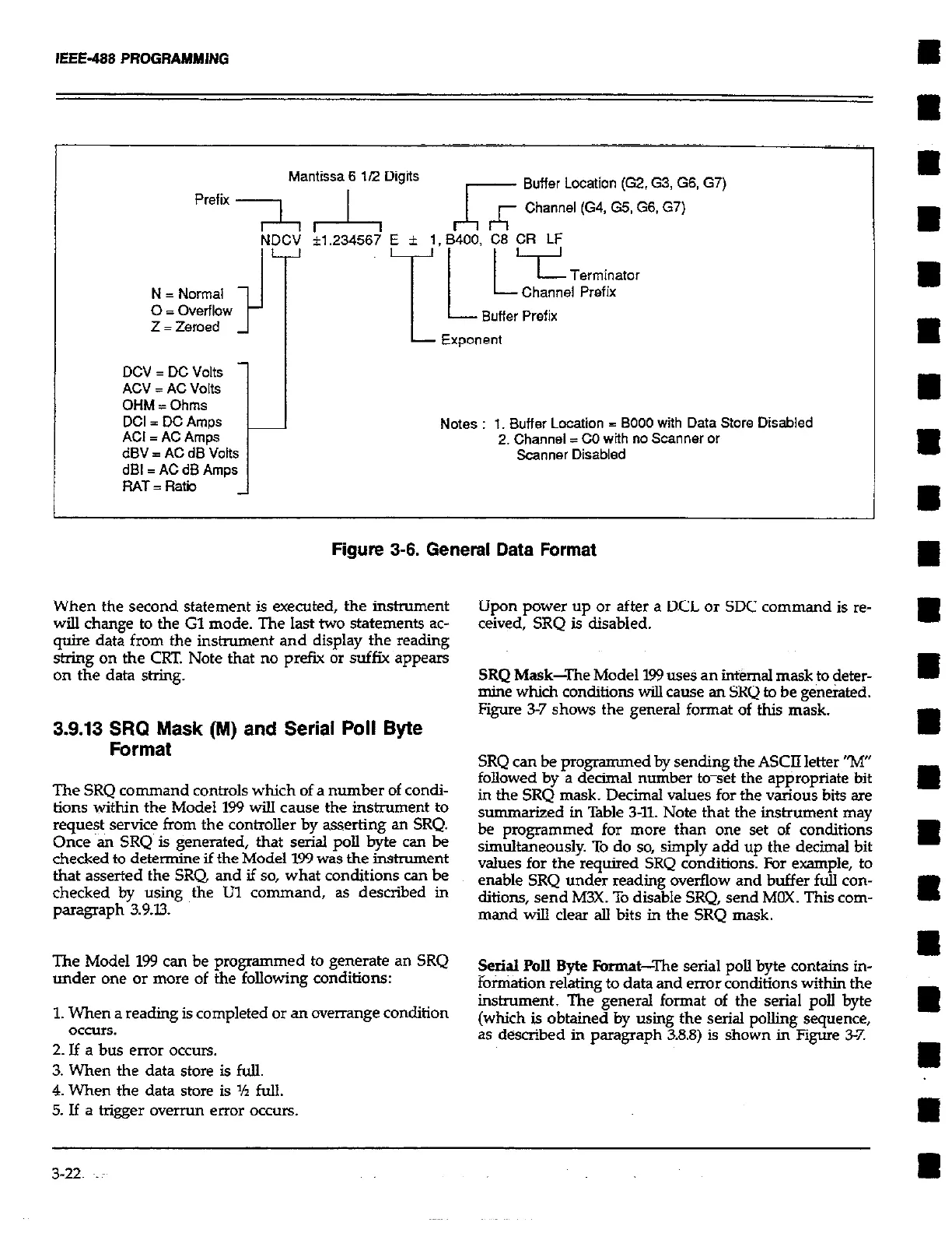
DCV = DC Volts
ACV = AC Volts
OHM = Ohms
dl3V I AC dB Volts
dBI = AC d5 Amps
RAT = Rata
Notes : 1. Buffer Location 3 BOO0 with Data Store Disabled
2. Channel = CO with no Scanner or
Scanner Disabled
Figure 3-6. General Data Format
When the second statement is executed, the instrument
will change to the Gl mode. The last two statements ac-
quire data from the instrument and display the reading
string on the CRT. Note that no prefu or suffix appears
on the data string.
3.9.13 SRQ Mask (M) and Serial Poll Byte
Format
The SRQ command controls which of a number of condi-
tions within the Model 199 will cause the instrument to
reque$ service from the controller by asserting an SRQ.
Once an SRQ is generated, that serial poll byte can be
checked to determine if the Model 199 was the instrument
that asserted the SRQ and if so, what conditions can be
checked by using the Ul command, as described in
paragraph 3.9.13.
The Model 199 can be programmed to generate an SRQ
under one or more of the following conditions:
1. When a reading is completed or an overrange condition
OCCUIS.
2. If a bus error occurs.
3. When the data store is full.
4. When the data store is ‘h full.
5. If a trigger overrun error occurs.
Upon power up or after a DCL or SDC command is re-
ceived, SRQ is disabled.
SRQ Mask-The Model 199 uses an internal mask to deter-
mine which conditions wiU cause an SRQ to be generated.
Figure 3-7 shows the general format of this mask.
SRQ can be programmed by sending the ASCII letter “M”
followed by a decimal number to-set the appropriate bit
in the SRQ mask. Decimal values for the various bits sre
summarized in Table 3-K Note that the instrument may
be programmed for more than one set of conditions
simultaneously. To do so, simply add up the decimal bit
values for the required SRQ conditions. For example, to
enable SRQ under reading overflow and buffer full con-
ditions, send M3X. To disable SRQ, send MOX. This com-
mand will clear all bits in the SRQ mask.
Serial PoII Byte Porma&The serial poIl byte contains in-
5x%&on relating to data and error conditions within the
instrument. The general format of the serial poll byte
(which is obtained by using the serial polling sequence,
as described in paragraph 3.88) is shown in Figure 3-7.