MAINTENANCE
1.~ Select the ohms function and the 3COQ range.
Ed. Repeat steps A through D for the remaining ohms
2. Connti the resistanw calibrator to the instkment as
shown in Figure 6-3.
3.20~ front panel calibration, press SHIFT’LCKAL and
proceed as follows:
A. With the lYO.OOOQ calibration displayed on the
Model 199, set the resistance calibrator to 190a.
8. After allowing sufficient time-foi fhe~ calibrator
resistance to settle, press the NEXT button. The
following message will be displayed for several
seconds:
WORKING
C. With the OOOlMOQ calibration point displayed, set
the resistawe calibrator to SHORT (On).
D. After waiting sufficient time for the calibrator
resistance to settle. mess the ENTER button. The
following message ‘will Abe displayed fro several
seconds:
raiges w&g Table 6-g as a guide.
I
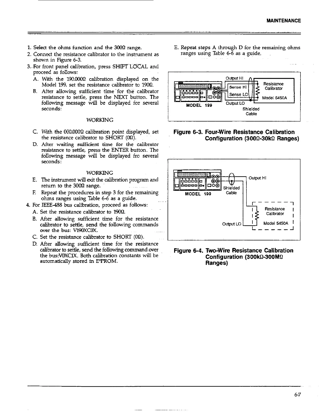
Oumut HI n,
4 Resistance
Shielded
Cable
Figure 6-3. Four-Wire Resistance Calibration
Configuration (300S30kQ Ranges)
ohms rang& using Table 6-6 as a guide.
4. For IEEE-488 bus calibration, proceed as follows:
A. Set the resistance calibrator to lYO’2.
B. After allowing sufficient time for the resistance
calibrator to settle, send the following commands
over the bus: VlYOXCOX.
WORKING
E. The instrument wi!.l tit the calibration program and
iim-
Output HI
return to the 300R range.
E Repeat the procedures in step 3 for the remaining
r----
2
-1
Resistance ,
Calibrator ,
Model 5450A 1
L-----J
C. Set the resistance calibrator to SHORT (On).
I
D. After allowing sufficient time for the resistance
calibrator to settle, send the following command_over
th-e bus:VOXCK Both calibration constants will be
Figure 6-4. Two-Wire Resistance Calibration
automatically stored in E’I’ROM.
Configuation (300kQ-300MQ
Ranges)
6-7