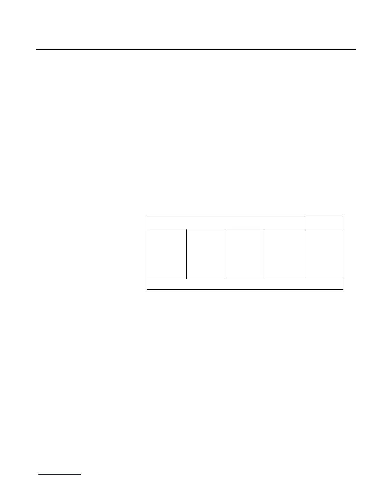
Test 304.1 — INPUT /100
Bank DC/OHM
Inputs Open
Expected Value 7 volts
Limits 0.7 volts
Fault Message INP SIG/100
Description
The ohms circuit current is set up the same as test 303.1. A 1mA current
flows into the OHM node but instead of flowing into the clamping circuit, it
flows through K101 (RESETK2 control line high) through Q102, Q101,
R117, and Q114 to LO.
Resistor R117 is a 100 to 1 divider. Therefore, 0.07V (7V/100) is seen at
the SIG/100 node. Q108 is turned on to switch the 0.07V through U113
(BUFCOM) to the A/D MUX which is configured for
×
100 gain. Measure
+7V at AD_IN.
Bit patterns
Bit pattern Register
QQ
87654321
—U106—
110v1111
QQ
87654321
—U109—
00101111
QQ
87654321
—U134—
1v10011v
—U130—
10111011
QQ
87654321
—U121—
10110001
ACDC_STB
MUX_STB
IC pins: Q8=11, Q7=12, Q6=13, Q5=14, Q4=7, Q3=6, Q2=5, Q1=4
Troubleshooting 2-39