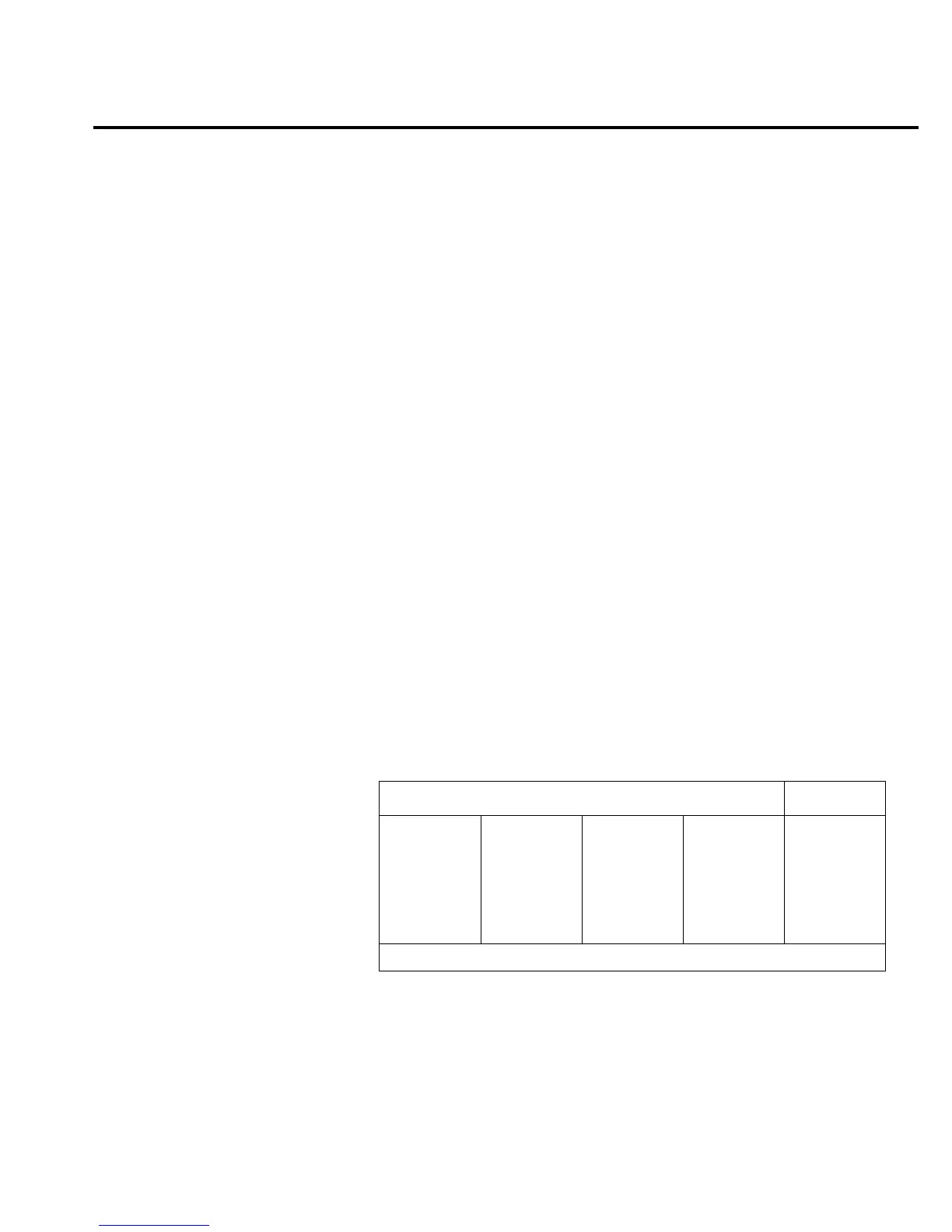
Test 600.2 — OHM/AMP
Bank AMP/OHM
Inputs INPUT HI to AMPS short
Expected Value 0.025 volts
Limits 0.015 volts
Fault Message .1 OHM SHUNT
Description This test requires a jumper wire from the INPUT HI jack to the AMPS
jack on the front panel. The +7V reference is switched to the ohms circuit
through U133. Q123 and Q125 are turned on to generate a 1mA current that
is routed to the INPUT HI jack. The signal path for this 1mA current is from
the +14V node through R194, Q125, Q119, Q120, K101 (pins 3 to 4) Q102,
Q101, through the parallel combination of R115, L109, and R324, then to the
INPUT HI jack.
The jumper wire then routes the 1mA into the AMP jack and through
K103 (SETK3 control line low so that pins 2 to 3 and 8 to 9 are closed). This
bypasses R205 and routes the 1mA through the 0.1Ω ohm resistor (R158). A
1mA current through 0.1Ω generates around 100µV which is sensed through
S101 and R142 to the AMPSHUNT node.
The AMPSHUNT signal is routed to S6 of U163 where it is switched to
the A/D MUX. The A/D MUX is configured for ×100 gain. Since this is a
very small voltage, trace resistance and circuit offsets greatly affect the ex-
pected voltage of 10mV. This test is useful to detect the presence of the prop-
er component operation and not so much their precision. Measure
approximately 25mV at AD_IN.
Bit patterns
Bit pattern Register
QQ
87654321
—U106—
110v1111
QQ
87654321
—U109—
00101111
QQ
87654321
—U134—
1v10011v
—U130—
11101011
QQ
87654321
—U121—
10110010
ACDC_STB
MUX_STB
IC pins: Q8=11, Q7=12, Q6=13, Q5=14, Q4=7, Q3=6, Q2=5, Q1=4
Troubleshooting 2-55

 Loading...


