Specifications A-9
DC Amps (cont’d)
DCI Reading Rates
4,5
Readings/Second with
Measurement Default Readings/Second to Memory Readings/Second to IEEE-488
9
Time Stamp to IEEE-488
9
PLC Aperture Bits Digits Autozero Off Autozero On Autozero Off Autozero On Autozero Off Autozero On
10 167 ms (200 ms) 29 7½ 6 ( 5 ) 2 (1.7) 6 ( 5 ) 2 (1.6) 6 ( 5 ) 2 (1.6)
2 33.4 ms (40 ms) 27 7½ 29 (25) 9 (7.6) 29 (24) 9 (7.4) 27 (22) 9 (7.4)
1 16.7 ms (20 ms) 26 6½ 56 (48) 47 (40) 55 (45) 46 (38) 50 (41) 42 (34)
0.2 3.34 ms (4 ms) 23 6½ 222 (197) 157 (140) 209 (186) 150 (133) 156 (139) 113 (100)
0.1 1.67 ms (2 ms) 22 5½ 334 (321) 178 (171) 310 (298) 168 (161) 186 (178) 124 (119)
0.02 334 µs (400 µs) 20 5½ 334 (334) 184 (184) 310 (310) 174 (174) 187 (187) 127 (127)
0.01 167 µs (167 µs) 19 4½ 387 (387) 186 (186) 355 (355) 176 (176) 202 (202) 128 (128)
0.01
7
167 µs (167 µs) 19 4½ 2000 (2000) 2000 (2000)
Speed and Accuracy 90 Days
ACCURACY
1,8
±(ppm of reading+ppm of range+ppm of range rms noise
4
)
1PLC
DFILT On, 1PLC 0.1PLC 0.01PLC
7
Range 10 Readings DFILT Off DFILT Off DFILT Off
200 µA 275+25+0 275+25+0.5 300+25+50 300+200+80
2 mA 275+20+0 275+20+0.5 300+20+50 300+200+80
20 mA 275+20+0 275+20+0.5 300+20+50 300+200+80
200 mA 300+20+0 300+20+0.5 325+20+50 325+200+80
2 A 600+20+0 600+20+0.5 625+20+50 625+200+80
PLC = Power Line Cycles. DFILT = Digital Filter.
Keithley Factory Calibration Uncertainty
Range ppm of reading
200 µA43
2mA 40
20 mA 55
200 mA 162
2 A 129
Factory calibration uncertainty represents traceability to
NIST. This uncertainty is added to relative accuracy
specifications to obtain absolute accuracies. The
uncertainties for each range are equal to the uncertainty of
the respective calibration sources.
DC Amps Notes
1 Specifications are for 1 power line cycle, autozero on, 10-reading repeat digital filter.
2 For T
CAL ± 1°C, following 55-minute warm-up. TCAL is ambient temperature at calibration
(23°C at the factory).
3 For T
CAL ± 5°C, following 55-minute warm-up.
4 Typical values. Peak-to-peak noise equals 6 times rms noise.
5 For on-scale readings, no trigger delays, internal trigger, digital filter off, normal autozero,
display off, SREAL format. These rates are for 60Hz and (50Hz). Rates for 400Hz equal those
for 50Hz.
6 Actual maximum burden voltage = (maximum burden voltage) × (I
MEASURED/I FULL SCALE).
7 In burst mode, display off. Burst mode requires autozero refresh (by changing resolution
or measurement function) once every 24 hours.
8 For T
CAL ±5°C, normal autozero. 1-year and 2-year accuracy can be found by applying the
same speed accuracy ppm changes to the 1-year or 2-year base accuracy.
9 Using Internal Buffer.
Settling Characteristics <500µs to 50ppm of step
size. Reading settling times
are affected by source
impedance and cable
dielectric absorption
characteristics.
Maximum Allowable Input 2.1A, 250V.
Overload Protection 2A fuse (250V), accessible
from front (for front input)
and rear (for rear input).
Autoranging Autoranges up at 105% of
range, down at 10% of
range.
DC In-Circuit Current
The DC in-circuit current measurement function allows a user to measure the current through
a wire or a circuit board trace without breaking the circuit.
When the In-Circuit Current Measurement function is selected, the 2002 will first perform a 4-
wire resistance measurement, then a voltage measurement, and will display the calculated
current.
TYPICAL RANGES
Current 100µA to 12A.
Trace Resistance 1mΩ to 10Ω.
Voltage ±200mV max. across trace.
Speed 4 measurements/second at 1 power line cycle.
Accuracy ±(5% + 500µA). For 1 power line cycle, autozero on, 10-
reading digital filter, T
CAL ±5°C, 90 days, 1 year or 2 years.
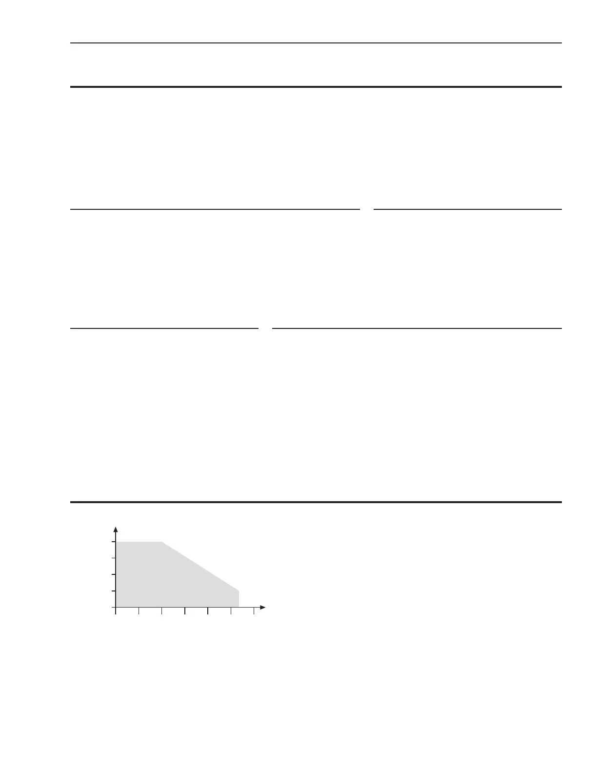
Measurement Range Chart
10Ω
1Ω
100mΩ
10mΩ
1mΩ
1mA 10mA 100mA 1A 10A 100A100µA
Measured Current
Trace Resistance
Specified
Measurement Range