Performance Verification
1-15
2. Characterize the 1GΩ resistor to within ±1,000ppm or
better using an accurate megohm bridge or similar
equipment. Record the characterized value where indi-
cated in Table 1-9. Also compute the limits based on the
value of R using the formula at the bottom of the table.
NOTE
The actual value of the 1GΩ resistor
should not exceed 1.05GΩ.
3. Set Model 2002 operating modes as follows:
A. From normal display, press CONFIG then Ω2.
B. Select SPEED, then press ENTER.
C. Select HIACCURACY, then press ENTER.
D. Select FILTER, then press ENTER.
E. Select AVERAGING, then press ENTER.
F. Using the cursor and range keys, set the averaging
parameter to 10 readings, then press ENTER.
G. Press EXIT to return to normal display.
4. Select the 2-wire ohms function (Ω2) and the 1GΩ
range on the Model 2002. (If the FILT annunciator is off,
press the FILTER key to enable the filter.)
5. Connect the 1GΩ resistor test box (from steps 1 and 2)
to the INPUT HI and LO terminals of the Model 2002.
(Be sure that the box shield is connected to INPUT LO.)
Allow the reading to settle.
6. Verify that the Model 2002 reading is within the limits
you calculated and recorded in Table 1-9.
1.8.6 Frequency accuracy verification
Frequency accuracy verification is performed by connecting
an accurate frequency source to Model 2002 inputs, and then
verifying that the frequency readings are within stated limits.
Use the procedure below to verify the frequency measure-
ment accuracy of the Model 2002.
1. Connect the frequency synthesizer to the Model 2002
INPUT terminals, as shown in Figure 1-9.
2. Turn on both instruments, and allow a one-hour warm-
up period before measurement.
Table 1-9
Limits for resistance verification (1G
Ω
range)
Characterized
resistor (R)
Reading limits
(1 year, 18°C to 28°C)
_________ GΩ _________ GΩ to _________ GΩ
* 1 year limits = R ± (0.002065R + 15,000)Ω
Where R = characterized value of 1GΩ resistor in ohms.
1GΩ range verification
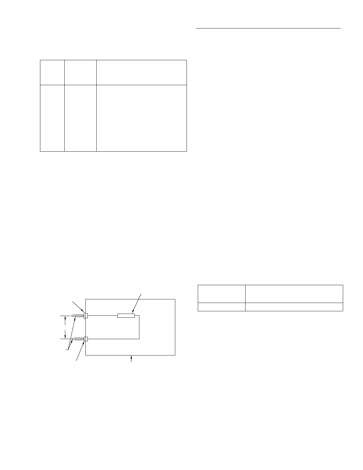
1. Mount the 1GΩ resistor and the banana plugs to the test
box, as shown in Figure 1-8. Be sure to mount the
banana plugs with the correct spacing. The resistor
should be completely enclosed in and shielded by the
metal test box. The resistor LO lead should be electri-
cally connected to the test box to provide adequate
shielding.
Table 1-8
Limits for resistance verification (20
Ω
-200M
Ω
ranges)
2002 Ω
range
Nominal
applied
resistance
Reading limits
(1 year, 18°C to 28°C)
20Ω 19Ω 18.9985025Ω to 19.0014975Ω
200Ω 190Ω 189.991277Ω to 190.008723Ω
2kΩ 1.9kΩ 1.89994714kΩ to 1.90005286kΩ
20kΩ 19kΩ 18.9994638kΩ to 19.0005362kΩ
200kΩ 190kΩ 189.989313kΩ to 190.010687kΩ
2MΩ 1.9MΩ 1.89981109MΩ to 1.90018891MΩ
20MΩ 19MΩ 18.9940619MΩ to 19.0059381MΩ
200MΩ 100MΩ 99.930910MΩ to 100.069090MΩ
Notes:
1. Limits shown include total absolute calibrator uncertainty (see Table
1-1) and factory calibration uncertainty (see specifications), and are
based on nominal calibration values shown. Recalculate limits using
Model 2002 relative accuracy specifications, factory calibration uncer-
tainty, and calibrator absolute uncertainty if calibrator resistance val-
ues differ from nominal values shown.
2. Use 4-wire connections and function for 20Ω-2MΩ ranges. Use 2-
wire connections and function for 20MΩ and 200MΩ ranges.
Figure 1-8
1G
Ω
resistor test box construction
Insulated
Plug
0.75"
HI
LO
Banana
Plugs
Non-insulated Plug
1GΩ Resistor (Keithley
part # R-289-1G)
Note: Resistor must be accurately characterized
before use (see text).
Metal
Test Box