Performance Verification
1-14
8. Set the calibrator output to 190Ω, and allow the reading
to settle.
9. Verify that the reading is within the limits stated in Table
1-8. (NOTE: Recalculate limits if calibrator resistance is
not exactly as listed.)
10. Repeat steps 8 and 9 for the 2kΩ through 2MΩ ranges
using the values listed in Table 1-8. (Do not use offset
compensation for the 200kΩ and 2MΩ ranges.)
20MΩ and 200MΩ range verification
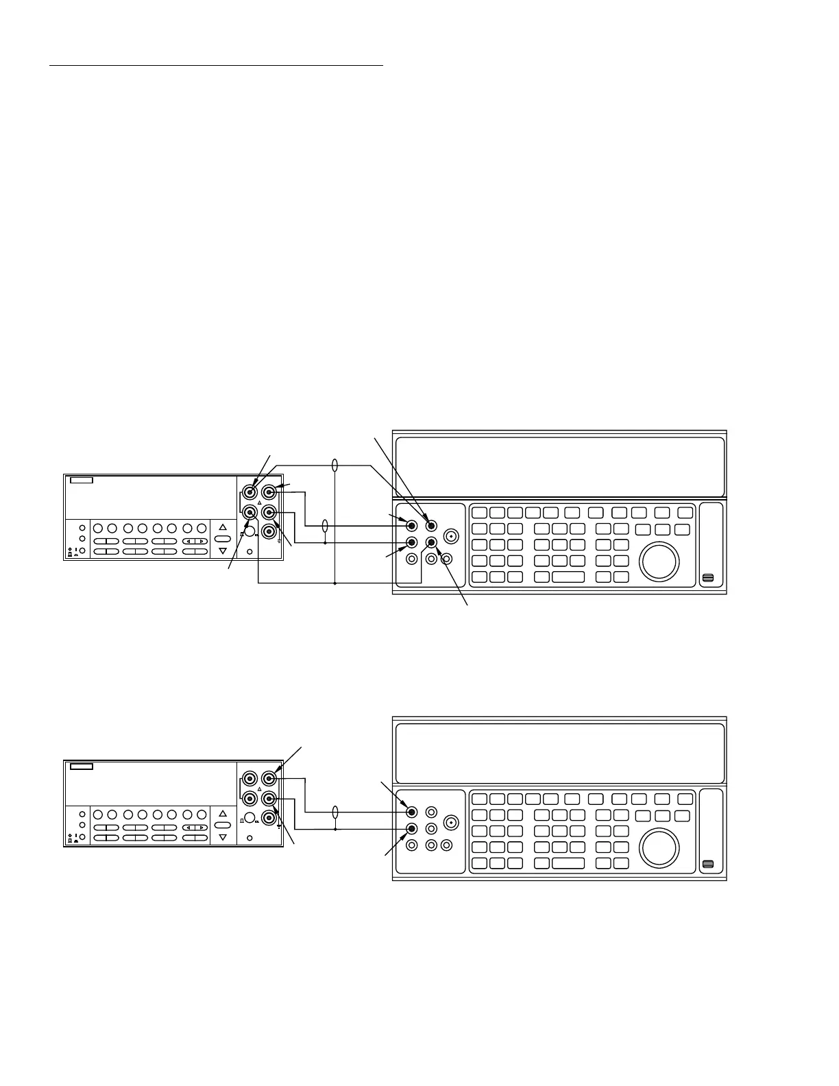
1. Connect the DC calibrator and Model 2002 using the 2-
wire connections shown in Figure 1-7.
2. Set the calibrator to the 2-wire mode (external sense
off).
3. Set Model 2002 operating modes as follows:
A. From normal display, press CONFIG then Ω2.
B. Select SPEED, then press ENTER.
C. Select HIACCURACY, then press ENTER.
D. Select FILTER, then press ENTER.
E. Select AVERAGING, then press ENTER.
F. Using the cursor and range keys, set the averaging
parameter to 10 readings, then press ENTER.
G. Press EXIT to return to normal display.
4. Select the Model 2002 Ω2 function, and change to the
20MΩ range. (If the FILT annunciator is off, press the
FILTER key to enable the filter.)
5. Set the calibrator to output 19MΩ, and allow the reading
to settle.
6. Verify that the reading is within the limits for the 20MΩ
range stated in Table 1-8. (NOTE: Recalculate limits if
actual calibrator resistance differs from value shown.)
7. Repeat steps 4 through 6 for the 200MΩ range (output
100MΩ).
Figure 1-6
Connections for resistance verification (20
Ω
-2M
Ω
ranges)
2002 MULTIMETER
Model 2002
5700A Calibrator (Output 4-wire Resistance)
Input HI
Output HI
Input
LO
Output
LO
Note : Use shielded cables to minimize noise.
Enable calibrator external sense mode.
Sense HI
Sense LO
Sense HI
Sense LO
1.90000000 kΩ OCmp
Figure 1-7
Connections for resistance verification (20M
Ω
and 200M
Ω
ranges)
2002 MULTIMETER
Input HI
Output HI
Input
LO
Output
LO
Model 2002
5700A Calibrator (Output 2-Wire Resistance)
Note: Use shielded cable to minimize noise.
Disable calibrator external sense mode.
19.0000000 MΩ