Performance Verification
1-13
1.8.5 Resistance verification
Resistance verification is performed by connecting accurate
resistance values to the instrument and verifying that Model
2002 resistance readings are within stated limits.
Follow the steps below to verify resistance measurement
accuracy.
CAUTION
Do not apply more than 1100V peak
between INPUT HI and LO or more
than 150V peak between SENSE HI and
LO, or instrument damage may occur.
20Ω – 2M range verification
1. Using shielded 4-wire connections, connect the Model
2002 to the calibrator, as shown in Figure 1-6. Be sure
to connect calibrator HI and LO terminals to the Model
2002 HI and LO terminals (including SENSE HI and
LO) as shown.
2. Turn on the Model 2002 and the calibrator, and allow a
four-hour warm-up period before making
measurements.
3. Set the calibrator for 4-wire resistance (external sense
on).
4. Restore Model 2002 factory default conditions, as
explained in paragraph 1.7.
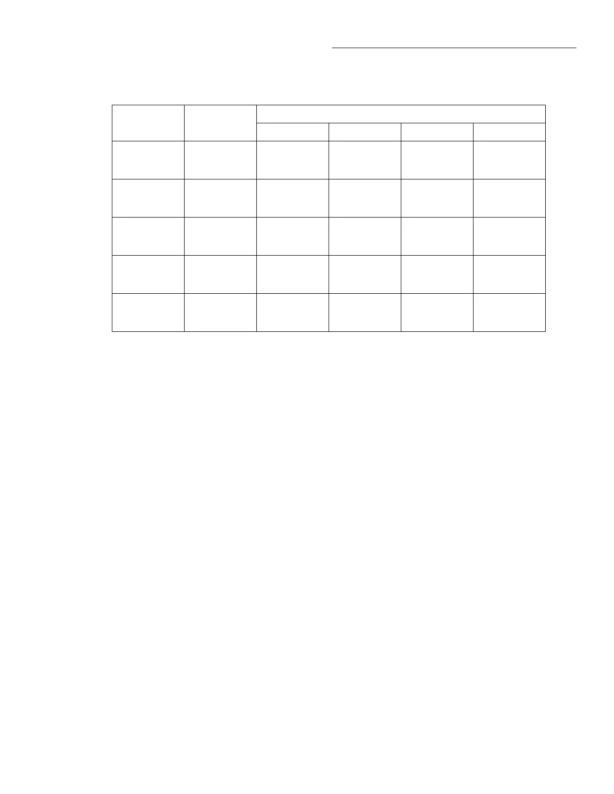
Table 1-7
Limits for AC current verification
2002 ACI
range
Applied AC
current
Reading limits (1 year, 18°C to 28°C)
40Hz 100Hz 1kHz 10kHz
200µA 190.000µA 188.260mV
to
191.740mV
189.562mV
to
190.439mV
189.210mV
to
190.790mV
189.020mV
to
190.980mV
2mA 1.90000mA 1.88355V
to
1.91645V
1.89657V
to
1.90344V
1.89742V
to
1.90258V
1.89742V
to
1.90258V
20mA 19.0000mA 18.8355V
to
19.1645V
18.9657V
to
19.0344V
18.9742V
to
19.0258V
18.9742V
to
19.0258V
200mA 190.000mA 188.355V
to
191.645V
189.657V
to
190.344V
189.742V
to
190.258V
189.685V
to
190.315V
2A 1.90000A 1.88250V
to
1.91750V
1.89552V
to
1.90449V
1.89390V
to
1.90610V
1.89105V
to
1.90895V
NOTE: Reading limits shown include total absolute uncertainty of recommended calibrator (see Table 1-1).
5. Set Model 2002 operating modes as follows:
A. From normal display, press CONFIG then Ω4.
B. Select SPEED, then press ENTER.
C. Select HIACCURACY, then press ENTER.
D. Select FILTER, then press ENTER.
E. Select AVERAGING, then press ENTER.
F. Using the cursor and range keys, set the averaging
parameter to 10 readings, then press ENTER.
G. Select OFFSETCOMP, then press ENTER.
H. Select ON, then press ENTER. (Note that OFFSET-
COMP cannot be used with the 200kΩ and 2MΩ
ranges.)
I. Press EXIT to return to normal display.
6. Select the Ω4 function, and place the instrument on the
20Ω range. (If the FILT annunciator is off, press the
FILTER key to enable the filter.)
7. Set the calibrator to output 19Ω, and allow the reading
to settle. Verify that the reading is within the limits stat-
ed in Table 1-8.
NOTE
Resistance values available in the Model
5700A calibrator may be slightly different
than the stated nominal resistance values.
Limits stated in Table 1-8 should be recal-
culated based on actual calibrator resis-
tance values.