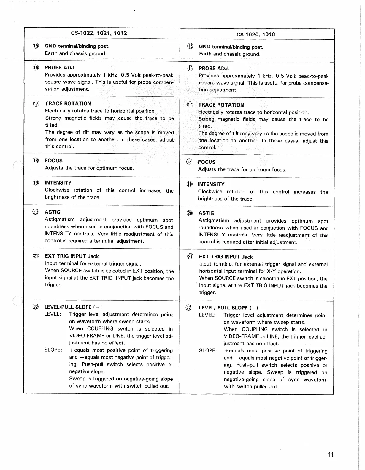
CS-1022, 1021, 1012
CS-1020, 1010
© GND terminal/binding post.
Earth and chassis ground.
(IJ) GND terminal/binding post.
Earth and chassis ground.
(0) PROBE ADJ.
Provides approximately 1 kHz, 0.5 Volt peak-to-peak
square wave signal. This is useful for probe compen-
sation adjustment.
© PROBE ADJ.
Provides approximately 1 kHz, 0.5 Volt peak-to-peak
square wave signal. This is useful for probe compensa-
tion adjustment.
(g) TRACE ROTATION
Electrically rotates trace to horizontal position.
Strong magnetic fields may cause the trace to be
tilted.
The degree of tilt may vary as the scope is moved
from one location to another. In these cases, adjust
this control.
© TRACE ROTATION
Electrically rotates trace to horizontal position.
Strong magnetic fields may cause the trace to be
tilted.
The degree of tilt may vary as the scope is moved from
one location to another. In these cases, adjust this
control.
(OD FOCUS
Adjusts the trace for optimum focus.
@> FOCUS
Adjusts the trace for optimum focus.
(0) INTENSITY
Clockwise rotation of this control increases the
brightness of the trace.
(0) INTENSITY
Clockwise rotation of this control increases the
brightness of the trace.
® ASTIG
Astigmatism adjustment provides optimum spot
roundness when used in conjunction with FOCUS and
INTENSITY controls. Very little readjustment of this
control is required after initial adjustment.
(§) ASTIG
Astigmatism adjustment provides optimum spot
roundness when used in conjuction with FOCUS and
INTENSITY controls. Very little readjustment of this
control is required after initial adjustment.
© EXT TRIG INPUT Jack
Input terminal for external trigger signal.
When SOURCE switch is selected in EXT position, the
input signal at the EXT TRIG INPUT jack becomes the
trigger.
(fj) EXT TRIG INPUT Jack
Input terminal for external trigger signal and external
horizontal input terminal for X-Y operation.
When SOURCE switch is selected in EXT position, the
input signal at the EXT TRIG INPUT jack becomes the
trigger.
@ LEVEL/PULL SLOPE (-)
LEVEL: Trigger level adjustment determines point
on waveform where sweep starts.
When COUPLING switch is selected in
VIDEO-FRAME or LINE, the trigger level ad-
justment has no effect.
SLOPE:
+ equals most positive point of triggering
and —equals most negative point of trigger-
ing.
Push-pull switch selects positive or
negative slope.
Sweep is triggered on negative-going slope
of sync waveform with switch pulled out.
@ LEVEL/ PULL SLOPE (-)
LEVEL: Trigger level adjustment determines point
on waveform where sweep starts.
When COUPLING switch is selected in
VIDEO-FRAME or LINE, the trigger level ad-
justment has no effect.
SLOPE:
+ equals most positive point of triggering
and —equals most negative point of trigger-
ing.
Push-pull switch selects positive or
negative slope. Sweep is triggered on
negative-going slope of sync waveform
with switch pulled out.
11
 Loading...


