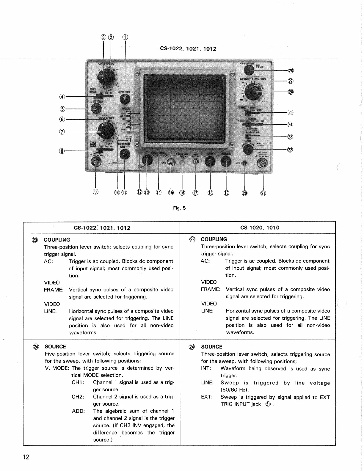
CS-1022,
1021, 1012
CS-1022,
1021, 1012
CS-1020,
1010
(§) COUPLING
Three-position lever switch; selects coupling for sync
trigger signal.
AC:
Trigger is ac coupled. Blocks dc component
of input signal; most commonly used
posi-
tion.
VIDEO
FRAME:
Vertical sync pulses of a composite video
signal are selected for triggering.
VIDEO
LINE:
Horizontal sync pulses of a composite video
signal are selected for triggering. The LINE
position is also used for all non-video
waveforms.
@) COUPLING
Three-position lever switch; selects coupling for sync
trigger signal.
AC:
Trigger is ac coupled. Blocks dc component
of input signal; most commonly used
posi-
tion.
VIDEO
FRAME:
Vertical sync pulses of a composite video
signal are selected for triggering.
VIDEO
LINE:
Horizontal sync pulses of a composite video
signal are selected for triggering. The LINE
position is also used for all non-video
waveforms.
(§) SOURCE
Five-position lever switch; selects triggering source
for the sweep, with following positions;
V. MODE: The trigger source is determined by ver-
tical MODE selection.
CH1:
Channel 1 signal is used as a
trig-
ger source.
CH2:
Channel 2 signal is used as a
trig-
ger source.
ADD:
The algebraic sum of channel 1
and channel 2 signal is the trigger
source.
(If CH2 INV engaged, the
difference becomes the trigger
source.)
(§) SOURCE
Three-position lever switch; selects triggering source
for the sweep, with following positions;
INT:
Waveform being observed is used as sync
trigger.
LINE:
Sweep is triggered by line voltage
(50/60 Hz).
EXT:
Sweep is triggered by signal applied to EXT
TRIG INPUT jack ® .
12
Fig.
5