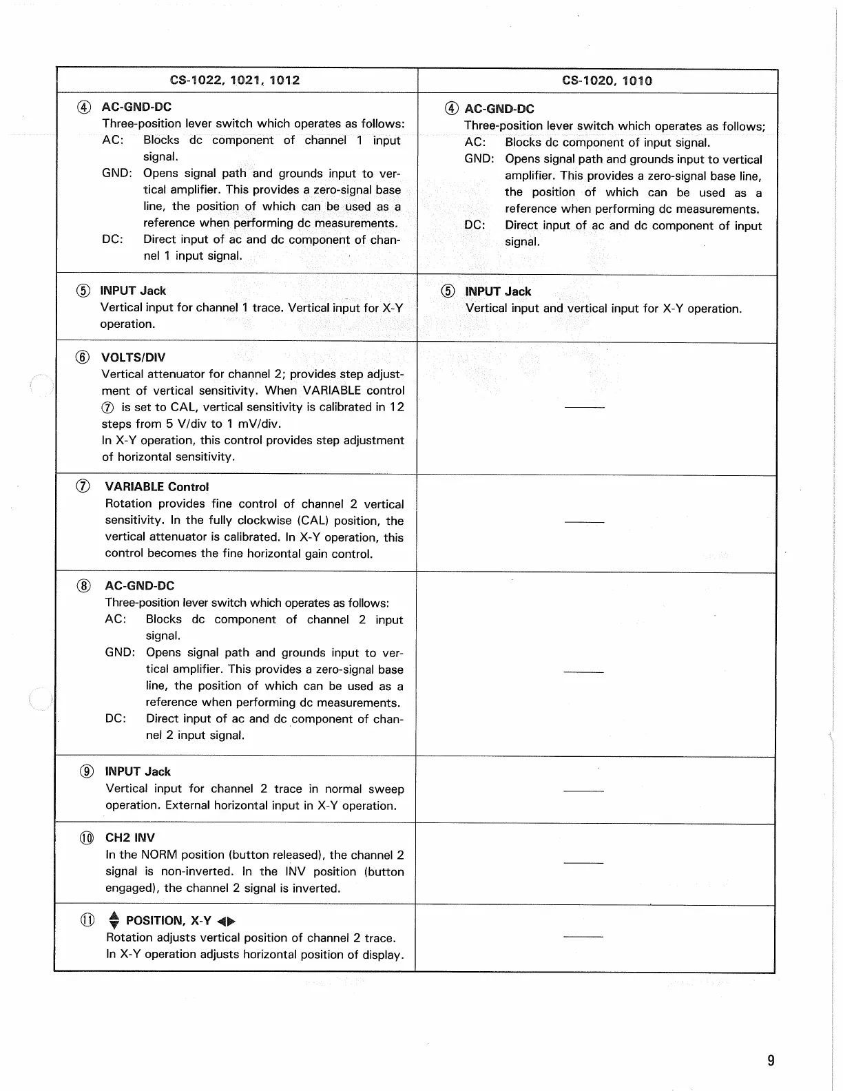
CS-1022, 1021, 101.2
CS-1020, 1010
© AC-GND-DC
Three-position lever switch which operates as follows:
AC:
Blocks dc component of channel 1 input
signal.
GND:
Opens signal path and grounds input to ver-
tical amplifier. This provides a zero-signal base
line,
the position of which can be used as a
reference when performing dc measurements.
DC:
Direct input of ac and dc component of chan-
nel 1 input signal.
(4) AC-GND-DC
Three-position lever switch which operates as follows;
AC:
Blocks dc component of input signal.
GND:
Opens signal path and grounds input to vertical
amplifier. This provides a zero-signal base line,
the position of which can be used as a
reference when performing dc measurements.
DC:
Direct input of ac and dc component of input
signal.
(5) INPUT Jack
Vertical input for channel 1 trace. Vertical input for X-Y
operation.
(5) INPUT Jack
Vertical input and vertical input for X-Y operation.
(D VOLTS/DIV
Vertical attenuator for channel 2; provides step adjust-
ment of vertical sensitivity. When VARIABLE control
(7) is set to CAL, vertical sensitivity is calibrated in 12
steps from 5 V/div to 1 mV/div.
In X-Y operation, this control provides step adjustment
of horizontal sensitivity.
(7) VARIABLE Control
Rotation provides fine control of channel 2 vertical
sensitivity. In the fully clockwise (CAL) position, the
vertical attenuator is calibrated. In X-Y operation, this
control becomes the fine horizontal gain control.
(8) AC-GND-DC
Three-position lever switch which operates as follows:
AC:
Blocks dc component of channel 2 input
signal.
GND:
Opens signal path and grounds input to ver-
tical amplifier. This provides a zero-signal base
line,
the position of which can be used as a
reference when performing dc measurements.
DC:
Direct input of ac and dc component of chan-
nel 2 input signal.
(J) INPUT Jack
Vertical input for channel 2 trace in normal sweep
operation.
External horizontal input in X-Y operation.
(Q) CH2 INV
In the NORM position (button released), the channel 2
signal is non-inverted. In the INV position (button
engaged), the channel 2 signal is inverted.
(Q) ^ POSITION, X-Y <<•
Rotation adjusts vertical position of channel 2 trace.
In X-Y operation adjusts horizontal position of display.
9