EasyManuals Logo

Keyprocessor Orion User Manual

Default Icon
29 pages
To Next Page IconTo Next Page
To Previous Page IconTo Previous Page
Page #17 background imageLoading...
Page #17 background image
17
Picture RS485
connection
Note! The Polyx must always be at the beginning of the communication line.
Remark: When using a shielded wire (conductive), the shield should be attached
on one side to earth () of the installation housing.
Note! The last Orion on the communication line must be provided of an EOL
jumper.
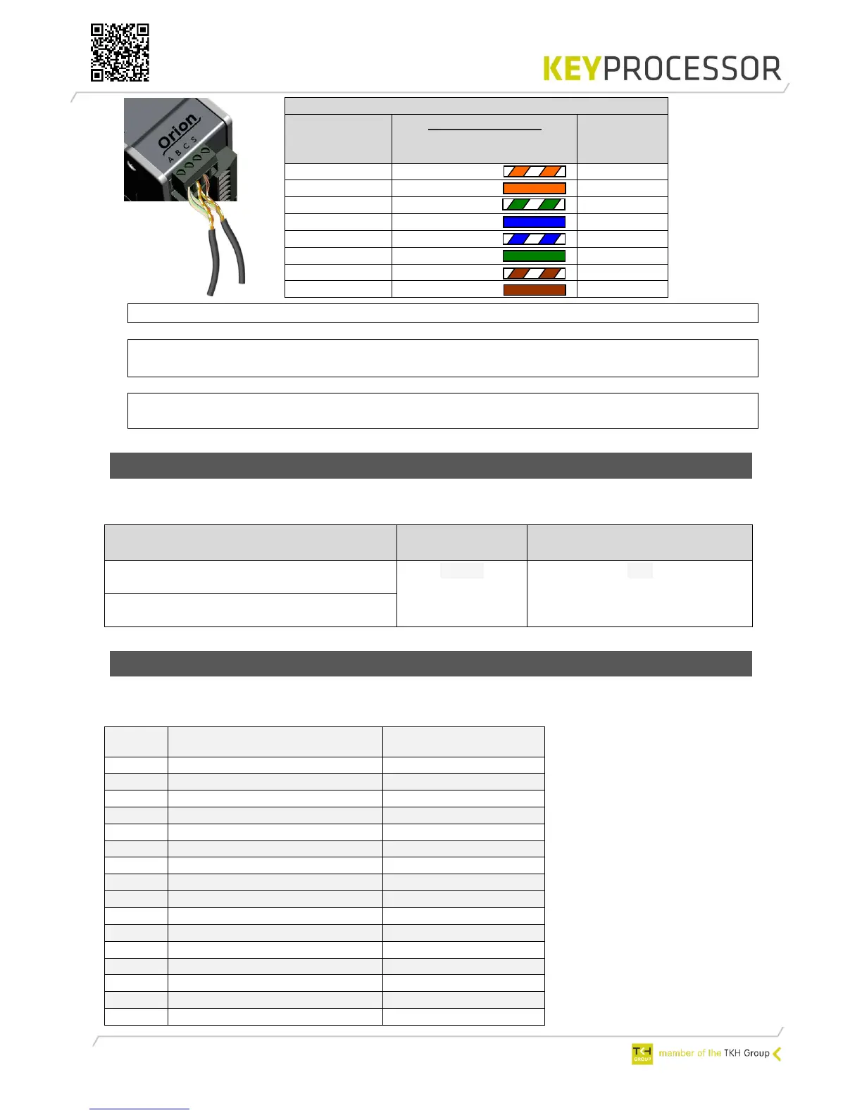
6.1.3 Cabling requirement
The required cable between the Polyx™ Network controller and the Orion(s) is displayed
below:
6.1.4 Card reader and IO connections
In the table below the labels-, connections- and the defaults are defined.
Reader & IO 1:
Connection: Orion <> Orion
Orion (I)
A B C S
RS485
TIA/EIA-568-B
Cable color
Orion (I)
A B C S
RS485
B
White/Orange
B
A
Orange
A
B
White/green
B
-
Blue
-
-
White/blue
-
A
Green
A
C
White/brown
C
C
Brown
C
Cable
Communication
type
Total bus length (meter)
CAT5/6 UTP four twisted pairs of 24AWG
copper conductors
RS485
600
Minimal 24AWG twisted pairs of 24AWG
copper conductors, shielded
Label
Description
iProtect default
C
GND (digital ground)
T1
Digital input (Reader tamper)
Door in latch mode
LD
LED control
D0
D0 / Data or Digital input*
D1
D1 / Clock or Digital input*
O1
Digital output
C
GND (digital ground)
+V
Reader power
A1
ADC input 1 **
Loop
A2
ADC input 2 **
Push button
A3
ADC input 3 **
Door status
C
GND (digital ground)
H1
High Power output
Door control
C
GND
O2
Digital output
Alarm
O3
Digital output

Questions and Answers:

Question and Answer IconNeed help?

Do you have a question about the Keyprocessor Orion and is the answer not in the manual?

Keyprocessor Orion Specifications

General IconGeneral
BrandKeyprocessor
ModelOrion
CategoryController
LanguageEnglish