30 Keysight Agile Signal Generator Service Guide
Troubleshooting
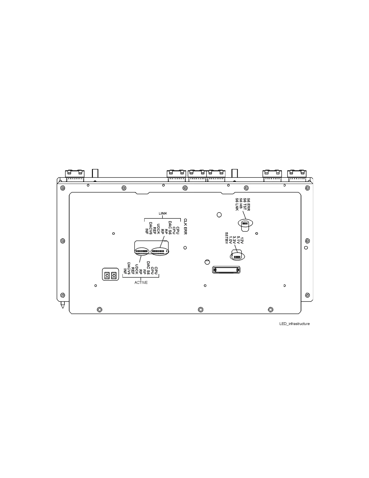
10.With the unit still off, on the A5 Infrastructure board, refer to Figure 1-3 to
visually inspect and verify that only the +5V_STBY (5STBY) status green
LED is lit. Other LED’s are off.
11.Turn the signal generator on, refer to Figure 1-3 to visually inspect and
verify the connectivity (LINK) LED’s are lit. During the boot-up routine, the
ACTIVE LED’s are blinking and then off when the boot-up is completed.
Also verify the Yellow Heart Beat (HB) LED is flashing.
— Power Supply LED’s: 12.1V, 5.1V, 3.3V, 1.0V, and 5STBY
— LINK LED’s: CPU, CPU, DAC S6, UDCK, REF, DAC V6, and INF
— Heart Beat: S6 HB
Figure 1-3 A5 Infrastructure Board LEDs
12.Position the signal generator with the bottom facing up.
13.With the unit still off, on the A2 Power Supply, refer to Figure 1-4 to
visually inspect and verify that only the +5S (5V Standby) status green LED
is lit. Other LED’s are off.

 Loading...