Step 3. Set the RP79xxA loads's list generator to generate a 100 Hz current waveform with a duty
cycle of 50%. Use the following commands to program the list:
FUNC:CURR - specifies current priority
VOLT:LIM MAX - specifies the voltage limit
CURR:MODE LIST - specifies current priority
LIST:CURR <low_value>,<high_value> - refer to test record card for low and high current values
LIST:DWEL 0.005, 0.005 - specifies a 100 Hz current waveform with a 50% duty cycle
LIST:COUN INF - sets the list count to infinity
INIT:TRAN - initiates the transient system
TRIG:TRAN - triggers the transient system
OUTP:ON - turns on the load
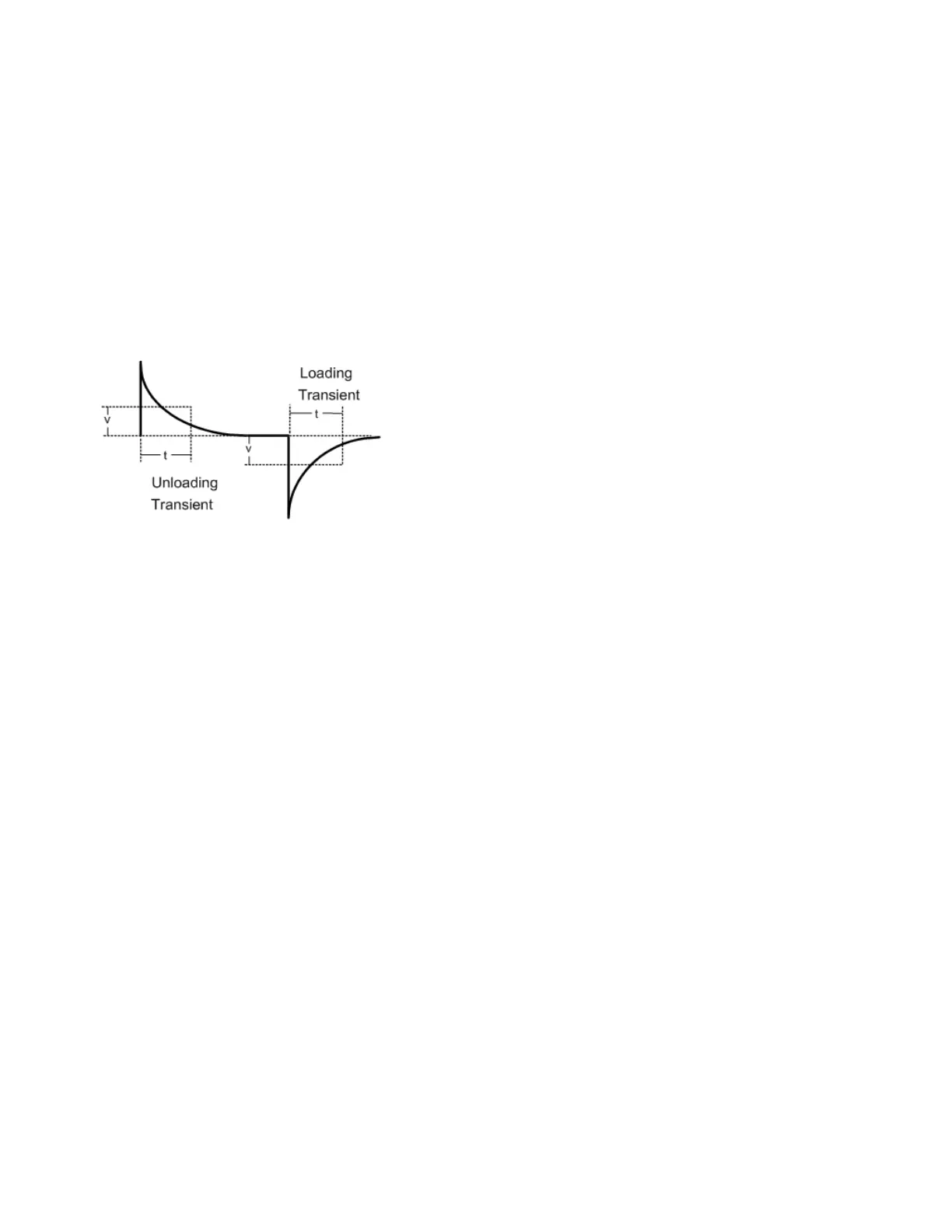
Step 4. Adjust the oscilloscope for a waveform similar to that shown in the following figure.
Step 5. The output voltage should return to within the specified voltage at the specified time after the
load change. Check both loading and unloading transients by triggering on the positive and negative
slope. Record the voltage at time “t” in the performance test record form under “Transient Response”.
Current Programming and Readback Accuracy
This test verifies that the current programming and measurement functions are within specifications.
Step 1. Turn off the unit under test. Connect the current shunt directly across the output terminals.
Connect the DMM directly across the current shunt (see Test Setup B). Note that the RP79xxA load is
not used in this portion of the test.
Step 2. Turn on the unit under test and program the instrument settings as described in the test record
form under “Current Programming & Readback, Min Current”. The output status should be “CC”, with
the output voltage close to zero. Wait 5 minutes for the temperature to settle.
Step 3. Divide the voltage drop (DMM reading) across the current shunt by the shunt resistance to
convert to amps and record this value. (Iout). Also, record the current measured by the instrument
over the interface. The readings should be within the limits specified in the test record form under
“Current Programming & Readback, Minimum Current”.
Step 4. Program the instrument settings as described in the test record form under “Current
Programming & Readback, High Current”. Wait 5 minutes for the temperature to settle.
Step 5. Divide the voltage drop (DMM reading) across the current shunt by the shunt resistance to
convert to amps and record this value.(Iout). Also, record the current reading measured by the
instrument over the interface. The readings should be within the limits specified in the test record form
under “Current Programming & Readback, High Current”.
Keysight RP7900 Series Operating and Service Guide 271
6 Verification and Calibration